en
6
Installation Indications, functions and options MessagesCommissioningOperation and function
Note
It must be possible to disconnect the device from the mains at any time.
Î Install the mains plug such that it is accessible at any time.
Î If this is not possible, install a switch that can be accessed.
Do not use the device if it is visibly damaged!
The power supply of the device must be 100 … 240 V~ (50 … 60 Hz). Attach exible
cables to the housing with the enclosed strain relief and the corresponding screws.
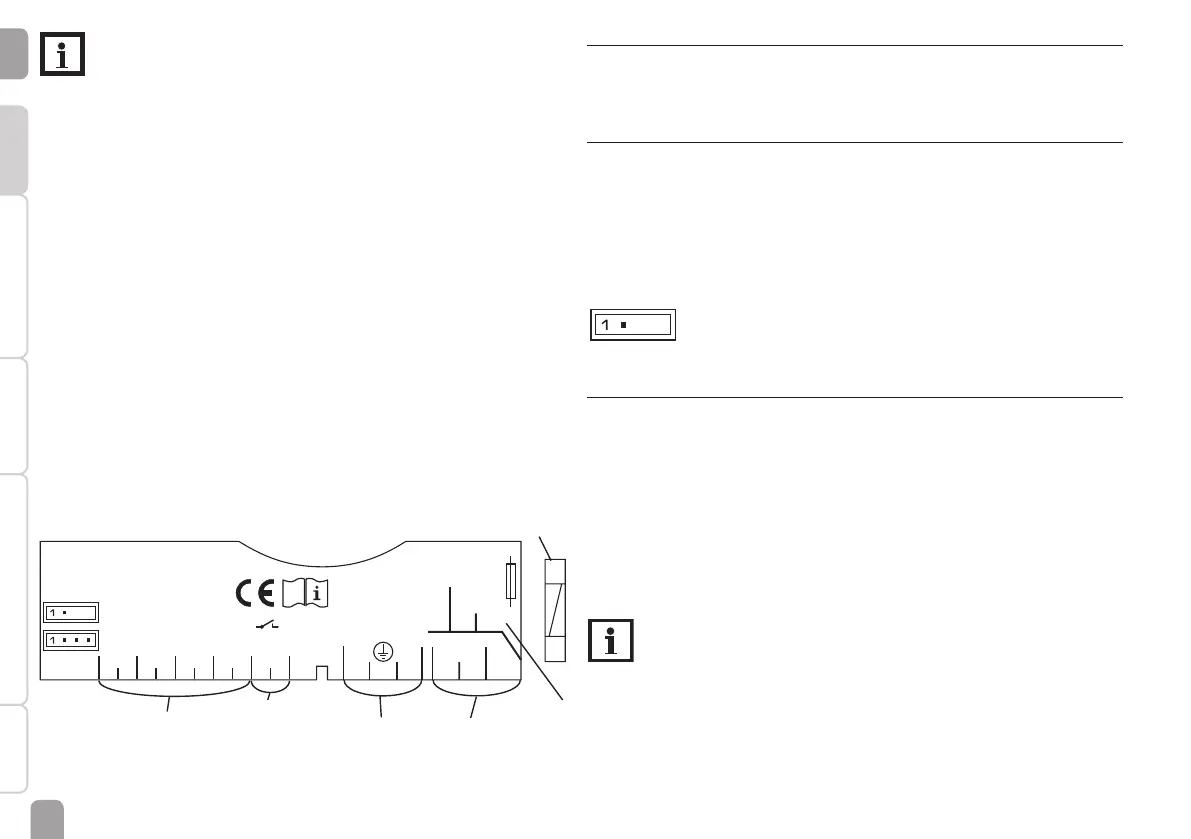
The controller is equipped with 1 semiconductor relay to which loads such as
pumps, valves, etc. can be connected:
Relay 1
18 = Conductor R1
17 = Neutral conductor N
13 = Protective earth conductor ⏚
The mains connection is at the following terminals:
19 = Neutral conductor N
20 = Conductor L
12 = Protective earth conductor ⏚
Connect the temperature sensors (S1 to S4) to the corresponding terminals
with either polarity:
1 / 2 = Sensor 1 (e. g. collector sensor)
3 / 4 = Sensor 2 (e. g. store sensor)
5 / 6 = Sensor 3 (e. g. store sensor top)
7 / 8 = Sensor 4 (e. g. return sensor)
1 (1) A 240 V~
LN
R1
N
2019
18
171615
14131212
IP 20
T2A
100 ... 240 V~
50-60 Hz
Temp. Sensor Pt1000
S2S1 S3 S4 VBus
PWM
VFD
3
4
5678910
Fuse
VBus
®
mains
terminals
load
terminals
sensor terminals
protective earth
conductor terminal
2.3 VFD Grundfos Direct Sensor™
The controller is equipped with 1 input for a digital VFD Grundfos Direct Sensor™
for measuring the ow rate and the temperature. Connection is made at the VFD
terminal (bottom left).
2.4 PWM output
Speed control of a HE pump is possible via a PWM signal. The pump has to be
connected to the relay as well as to the PWM output of the controller. Power is
supplied to the HE pump by switching the corresponding relay on or off.
The two pins on the left-hand side of the connector marked PWM are the control
output for a pump with PWM control input. The two pins on the right-hand side
are not used.
2
1
1 (1) A 240 V~
LN
R1
N
2019
18
17161514131212
IP 20
T2A
100 ... 240 V~
50-60 Hz
Temp. Sensor Pt1000
S2S1 S3 S4 VBus
PWM
VFD
3
4
5678910
1 = PWM output 1, control signal
2 = PWM output 1, GND
2.5 Data communication / Bus
The controller is equipped with the RESOL VBus
®
for data transfer and energy
supply to external modules. The connection is to be carried out at the terminals
marked VBus (either polarity).
One or more RESOL VBus
®
modules can be connected via this data bus, such as:
• RESOL DL2 Datalogger
• RESOL DL3 Datalogger
Furthermore, the controller can be connected to a PC or integrated into a net-
work via the VBus
®
/USB or VBus
®
/LAN interface adapter (not included). Different
solutions for visualisation and remote parameterisation are availabe on the RESOL
website www.resol.com.
Note
More accessories on page 27.
 Loading...