8
www.restek.com
11.0 Interpreting the Results
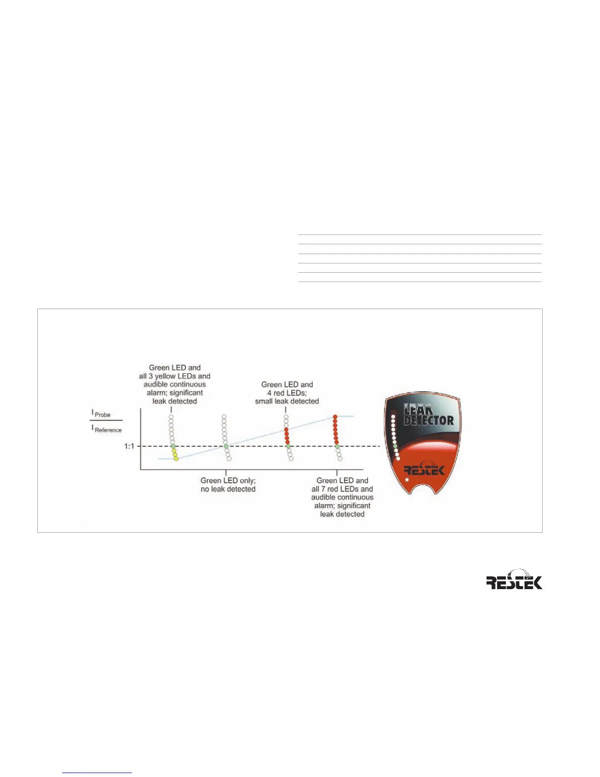
Figure 5 illustrates the Leak Detector’s LED light response
range. The greater the number of red or yellow LED lights lit
correlates in general to the size of the leak. NOTE: The Leak
Detector is not a quantitative device, rather it is designed to
detect leaks in gas line connections commonly associated with
laboratory equipment
**This unit is NOT designed for determining leaks of combustible gases. A combustible gas detector should be used for determining combustible gas leaks in a
hazardous environment.
Minimum Detectable Indicating
Leak Rate LED Light
Gas (atm cc / sec.) Color
Helium 1.0 x 10
-
5
Red
Hydrogen** 1.0 x 10
-5
Red
Nitrogen 1.4 x 10
-3
Yellow
Argon 1.0 x 10
-
4
Yellow
Carbon dioxide 1.0 x 10
-
4
Yellow
Figure 5 LED light response chart for the Leak Detector. A 1:1 ratio of IProbe : IReference indicates no leak present. Red LED
lights indicate the presence of one or more of the following gases: helium or hydrogen. Yellow LED lights indicate the
presence of one or more of the following gases: nitrogen, argon, or carbon dioxide.