STEP 4: FRONT WHEEL
Flip the bike over so it's resting on the saddle and handlebars.
I
2 - Remove the plastic protector from the fork dropouts.
3 - Loosen the axle nuts on the unattached front wheel.
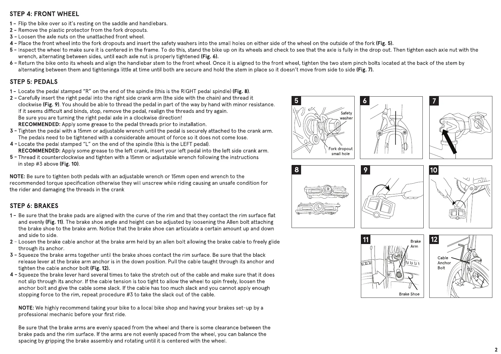
4 - Place the front wheel into the fork dropouts and insert the safety washers into the small holes on either side of the wheel on the outside of the fork (Fig. 5).
5 - Inspect the wheel to make sure it is centered in the frame. To do this, stand the bike up on its wheels and check to see that the axle is fully in the drop out. Then tighten each axle nut with the
wrench, alternating between sides, until each axle nut is properly tightened (Fig. 6).
6 - Return the bike onto its wheels and align the handlebar stem to the front wheel. Once it is aligned to the front wheel, tighten the two stem pinch bolts located at the back of the stem by
alternating between them and tighteninga little at time until both are secure and hold the stem in place so it doesn't move from side to side (Fig. 7).
STEP 5: PEDALS
I-
Locate the pedal stamped "R" on the end of the spindle (this is the RIGHT pedal spindle) (Fig. 8).
2 - Carefully insert the right pedal into the right side crank arm (the side with the chain) and thread it
clockwise (Fig. 9). You should be able to thread the pedal in part of the way by hand with minor resistance.
If it seems difficult and binds, stop, remove the pedal, realign the threads and try again.
Be sure you are turning the right pedal axle in a clockwise direction!
RECOMMENDED: Apply some grease to the pedal threads prior to installation.
3 - Tighten the pedal with a 15mm or adjustable wrench until the pedal is securely attached to the crank arm.
The pedals need to be tightened with a considerable amount of force so it does not come lose.
4 - Locate the pedal stamped "L" on the end of the spindle (this is the LEFT pedal).
RECOMMENDED: Apply some grease to the left crank, insert your left pedal into the left side crank arm.
5 - Thread it counterclockwise and tighten with a 15mm or adjustable wrench following the instructions
in step #3 above (Fig. 10).
NOTE: Be sure to tighten both pedals with an adjustable wrench or 15mm open end wrench to the
recommended torque specification otherwise they will unscrew while riding causing an unsafe condition for
the rider and damaging the threads in the crank
STEP 6: BRAKES
I - Be sure that the brake pads are aligned with the curve of the rim and that they contact the rim surface flat
and evenly (Fig. II). The brake shoe angle and height can be adjusted by loosening the Allen bolt attaching
the brake shoe to the brake arm. Notice that the brake shoe can articulate a certain amount up and down
and side to side.
2 - Loosen the brake cable anchor at the brake arm held by an allen bolt allowing the brake cable to freely glide
through its anchor.
3 - Squeeze the brake arms together until the brake shoes contact the rim surface. Be sure that the black
release lever at the brake arm anchor is in the down position. Pull the cable taught through its anchor and
tighten the cable anchor bolt (Fig. 12).
4 - Squeeze the brake lever hard several times to take the stretch out of the cable and make sure that it does
not slip through its anchor. If the cable tension is too tight to allow the wheel to spin freely, loosen the
anchor bolt and give the cable some slack. If the cable has too much slack and you cannot apply enough
stopping force to the rim, repeat procedure #3 to take the slack out of the cable.
NOTE: We highly recommend taking your bike to a local bike shop and having your brakes set-up by a
professional mechanic before your first ride.
Be sure that the brake arms are evenly spaced from the wheel and there is some clearance between the
brake pads and the rim surface. If the arms are not evenly spaced from the wheel, you can balance the
spacing by gripping the brake assembly and rotating until it is centered with the wheel.
Safety
washer
Fork dropout
small hole
o
11
Brake
Arm
Brake Shoe
O
6
12
Anchor
Bolt
2
 Loading...