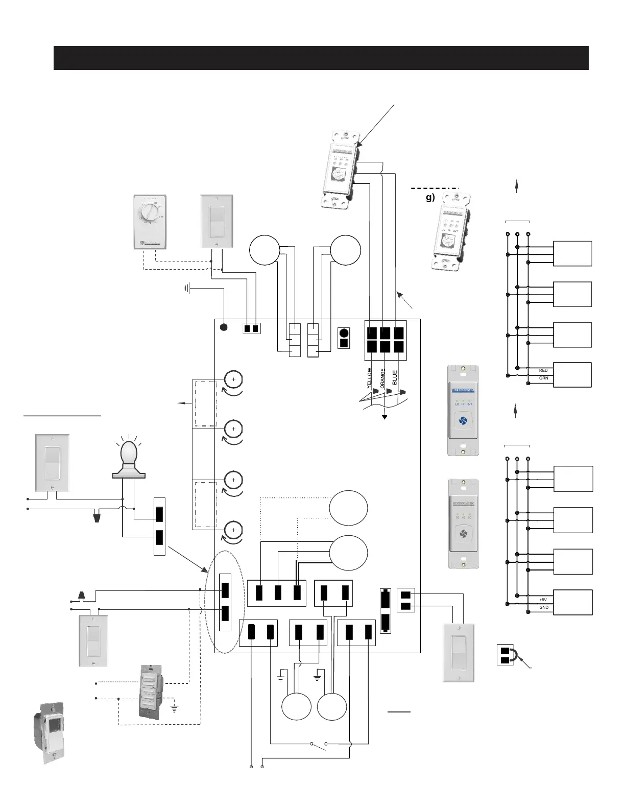
Wiring Diagram : Superior ECM
2
LINE
LINE
SUPPLY
NEUT
LINE
EXHAUST
LINE
NEUT
DAMP NC
NEUT
DAMP NO
NEUT
LINE SW
On
Off
Remote
e)
(HV-High Voltage)
ON/OFF
Low HighLow High
Exhaust
Fan Speed
Supply
Fan Speed
4 - Speed Controller for Manual Balancing
and Air Flow Adjustment
(Turn the Knob clockwise
to increase speed)
or
120 Vac / 1 / 60Hz
Power Supply
Low
b)
Note: Same power source can be
used for wall switch,Time delay switch
(TC100-120 & TC100-120P) and HRV / ERV
TC100-120P
d) TC100-120
RED
BLACK
WHITE
Ground
120 Vac / 1 / 60Hz
Power Supply
b)
c)
Hi
Low
Low Voltage
Speed
Contact
(Dry contact)
GND DAT 5V
RED
WHITE
BLACK
Low Voltage
NC
C
NO
Interloc
k
(These connections
must be done inside
the electrical box)
a)
Furnace, Fan Coil,
Heat Pump
Interlock
RED
YEL
g)
(Also available without
OFF mode)
GRN
Note:
Up to 4 Timer Switches (TC 100-5V)
and one intermittent switch (IC 100-5V)
can be connected to control board of
HRV/ERV by using three 24 AWG (min.)
standard Copper wires as shown.
Maximum total wire length 75ft.
(see option 2)
Option 2:
Timer
Switch
2
Timer
Switch
3
Timer
Switch
4
to Control
Board
YEL
RED
GRN
+5 DAT GND
YEL
RED
GRN
YEL
RED
GRN
(TC100-5V)
YEL
RED
GRN
Intermittent
OR Timer
Switch 1
FAN
Exhaust
FAN
Supply
AC connection
Door Safety switch
Temp
Sensor
Exhaust
FAN
motor
f)
HRV/ ERV
Hi / Low
120 Vac / 1 / 60Hz
Power Supply
Light / Switch Option
b)
Light
On / Off
Remote
0n/0ff
HV
Jumper
(remove jumper to install
master ON/OFF switch)
Ext. Interlock
OR
Ground
DC connection
Note:
Make sure, the Line must be
connected to Line and Neutral
connected to Neutral. Unit will not
function if not connected correctly.
OptionalAccessories(Not Supplied)
a) Timer S
witch (TC100)(old/new)
b) Wa
llSwitch
c) Dehumidistat
d) Time D
elay Switch (TC100-120 & TC100-120P)
e) Master On
/Off Switch for HRV/ERV
f) Light
g) Intermittent S
witch (old/new)
Timer
Switch
4
to Control
Board
+5 DAT GND
(TC100-5V)
DAT
+5V
GND
RED
WHIT
E
BLAC
K
RED
WHIT
E
BLAC
K
DAT
+5V
GND
DAT
+5V
GND
DAT
+5V
GND
NEW
Intermittent
OR Timer
Switch 1
NEW
Timer
Switch
2
NEW
Timer
Switch
3
NEW
New
Intermittent Switch
(TC150-5V)
New
Timer Switch (TC100-5V)
+
-
120 VAC / 1 / 60Hz
Power Supply
+
-
+
Hi
-
+
-
Supply
FAN
YELLOW
BLUE
WHITE
WHITE
BLUE
YELLOW
YELLOW
ORANGE
YELLOW
ORANGE
WHITE
RED
RED
BLACK
BLK
WHT
GREEN
BROWN
BLUE
BLACK
GREEN
BROWN
motor
BLACK
WHITE
For built-in
Damper
internal damper
connection
(forward /
reverse motor)
For external
Damper
damper
connection (single
stack motor)
BLUE
WHT