!
C AU T I O N
!
The HRV a n d all c o n d e n s a t e l ines m u s t be insta l l e d in a s p a c e w h e r e t h e t e m p e r a t u r e
is m a i n t a i n e d a b o v e t h e f r e e z i n g p o i n t or f r e e z e pr o t e c t i o n m u s t be p r o vi d e d .
Drain Spout
½”I.D.
Drain Pipe
“ T ” Connector
Zip Tie
to Drain
“P” Trap
HRV/ERV Steel Housing
Steel washer
Nut
Drain Spout
Drain Spout Assembly
Plastic DrainPan
Rubber washer
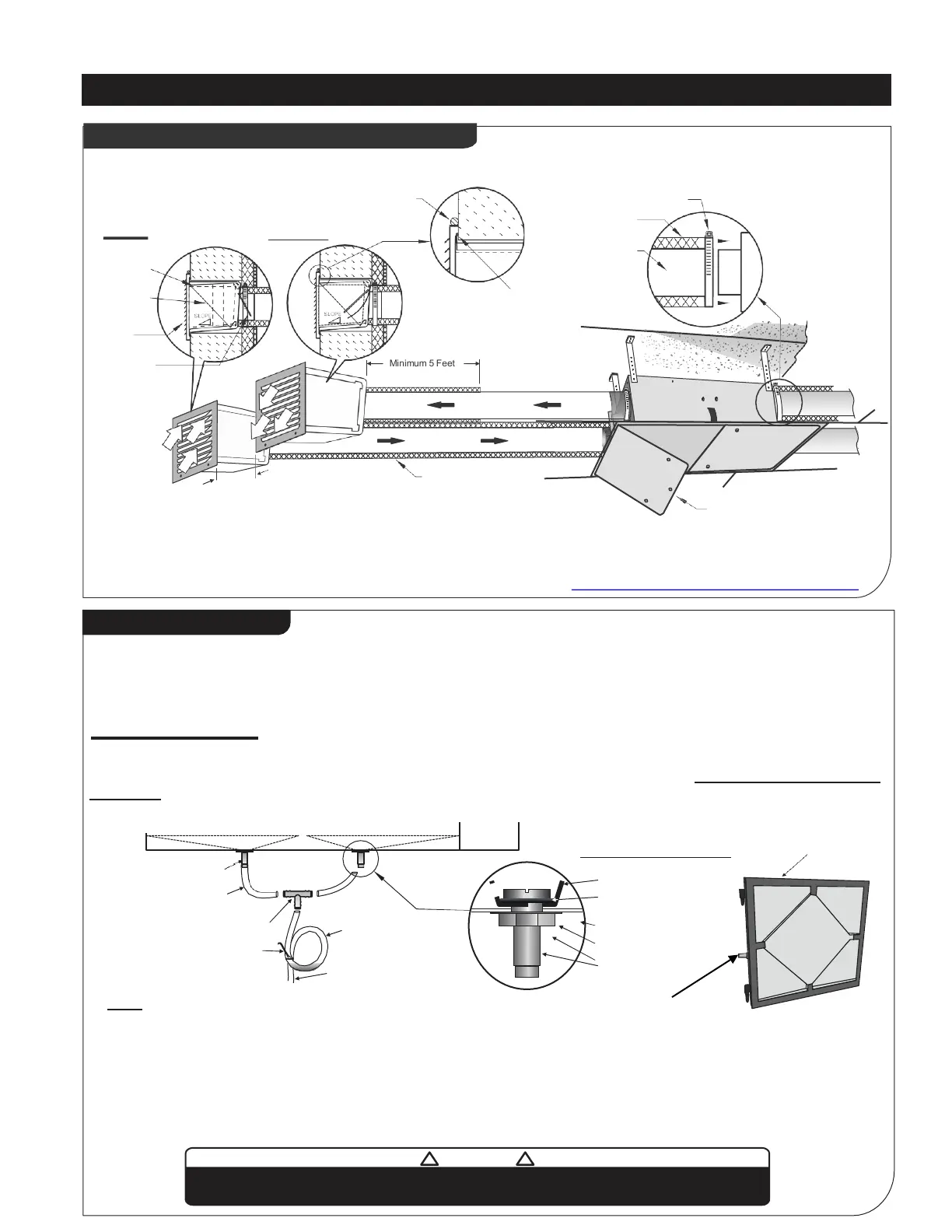
HRV and ERV Typical Installations (cont’d)
6
Lid
Drain Connection
During defrost cycle the HRV unit may produce some condensation and the water should flow into a nearby drain.
The HRV cabinet has pre-punched holes(two on side and one on the door) for the drain, in order to keep the drain pan
intact, hand tighten the plastic drain spout to the unit using the gasket and nuts.
For Vertical installation
Cut two sections of ½" drain pipe and connect the other ends to the drain spout then connect to “T” connector. Connect a
drain line and create a P-trap to prevent the unit from unpleasant odours from drain source. Tape
or fasten base to avoid
any
bends.
(For vertical installation)
Drain Pan
Drain Pan
Use this drain for
horizontal installation
Note:
- For Horizontal installation,
connect only 1 drain spout assembly on lid / door.
cut one ½’’ drain pipe and connect one end to the drain spout and the other
end to the drain line. Don't forget to create a P-trap as shown above.
- HRV must be connected to drain.
- ERV does not required any drain. However,
we recommend to connect ERV to drain in
areas where extreme cold weather conditions are expected.
Minimum 5 Feet
Exhaust
Insulation
CAULKING GRILLE
- 3 SIDES ONLY, NOT ON BOTTOM
CAULKING WALLBOX
- CAULK WALLBOXTO
STRUCTURE ON ALL 4 SIDES
Distance
“X”
“Single Vents Only”
Metal Clamp
Insulation
Duct
Backdraft
Damper
Grille
Intake
Insulation
Wallbox
Access Door
-Use appropriate access door size and install on proper
location for easy access to all HRV/ERV components fo
r
r
outine check and maintenance of the unit.
For more info visit
http://www.reversomatic.com/HRV&ERV/Accessories
Typical Installations of Single Vents & Access door
*Re - Circulation Efficiency
If distance “X” is 5ft - 99.7%
“X” is 3ft -96.5%
Note:
-Fresh air intake and supply duct must be totally insulated. Exhaust duct
must be 5 feet insulated from the wall. In colder climate, it is recomm
ended
to i
nsulate all exhaust and supply ducts.
-
Check your building code for Insulation requirement