GND
DAT
5V
NC C
NO
NO
C
NC
(Thes e connections
must be done inside
the electrical box)
FOUR WIRE
GND
DAT
5V
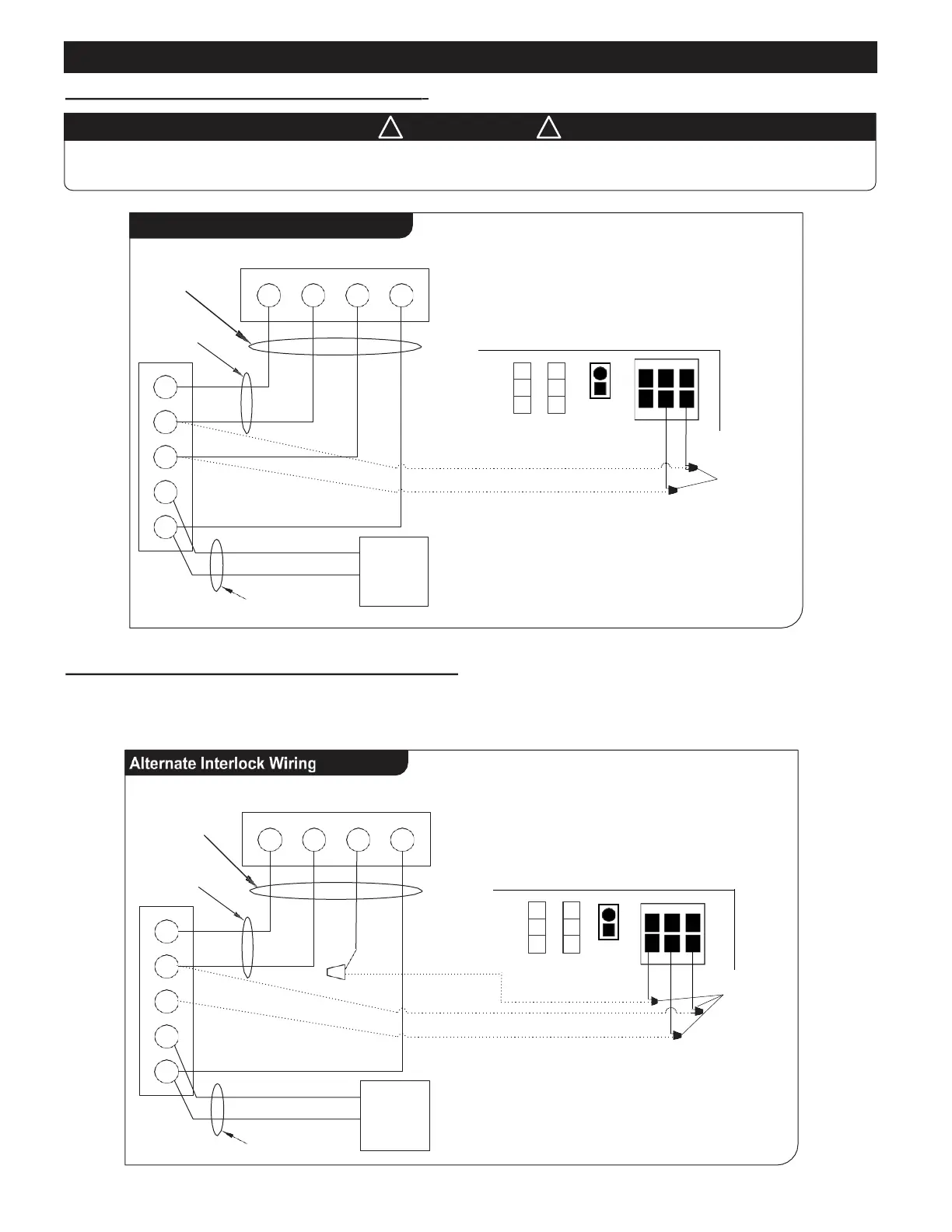
For a furnace connected to a cooling system:
On some older thermostats, energizing the R and G terminals at the furnace has the effect of energizing Y at the
thermostat and thereby turning on the cooling system. If you identify this type of thermostat, you must use the
“Alternate Interlock Wiring”.
Furnace / Fan-Coil / Heat Pump Interlock:
Standard Interlock Wiring
W
R
G
Y
C
TW OW IRE
heating only
Cooling
System
THERMOSTAT TERMINALS
W R G Y
TW OWIRE
!
W A R N I N G
!
Never connect a 120 volt AC circuit to the terminals of the furnace/fan-coil/heat pump interlock (Standard Wiring).
Only use the low voltage class 2 circuit.
Note: These Connections must be done inside the electrical box
NO
C
NC
(Thes e connections
must be done inside
the electrical box)
FOUR WIRE
GND
DAT
5V
SUPERIOR ECM CONTROLBOARD
W
R
G
Y
C
TW OWIRE
heating only
Cooling
System
THERMOSTAT TERMINALS
W R G Y
TW OW IRE
Note: These Connections must be done inside the electrical box
YELLOW
Temp
Sensor
Temp
Sensor
ORANGE
BLUE
Furnace, Fan Coil,
Heat Pump
Interlock
Furnace, Fan Coil,
Heat Pump
Interlock
SUPERIOR ECM CONTROLBOARD
Wiring Diagram (cont’d)
3
Ex Su
Ex Su
ORANGE
BLUE