Home
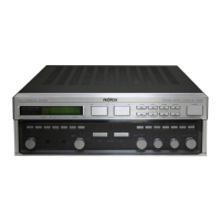
Revox
Amplifier
B251
Revox B251 User Manual
4
of 1
of 1 rating
Go to English
55 pages
Give review
Manual
Specs
To Next Page
To Next Page
To Previous Page
To Previous Page
Loading...
1
SIART-UP
PROCEDURE
1.1
General
1.1.1
Gonnecting
the
audio
sources
Audio
sources
are
devices
such
as
turntables,
tuners,
and
tape
recorders
that
supply
audio
signals.
Tape
recorders
can
both
transmit
and
receive
(record)
signals
whrch
means
thatthe
audio
path
must
be
connected
in
both
direc-
tions.
Turntable:
-
Connect
cable
(Cinch
connector)
of
the
turntable
to
the
PHONO
input.
lf
the
turn-
table
is
equipped
with
a
moving
magnet
cartridge,
the
input
MM
156l
is
used.
Turn-
tables
with
moving
coil
cartridges
are
con-
nected
to
the
input
MC
[57]
(retrofittable
option.
part
No.
78670).
-
Connect
the
skinned
end
of
the
thin
ground
wire
to
the
screw-type
terminal
[60]
(loosen
hexagon
nut,
slide
stranded
wire
under
it
and
retighten
nut).
t57I
[56]
Compact
Disc
digital
audio
player
(cable
C2C
210)
-
The
socket
for
connecting
a
CD
digital
au-
dio
player
is
labeled
with
DISC
[51].
Tuner
(cable
C2C
210)
-
Connecttuner
output
lfor8261:
FIXED
OUT-
PUT)
to
the
amplifier
input
TUNER
1501.
A
second
tuner
(e.9.
AM
receiver)
can
be
connected
to
the
AUX
input
t551.
Reel-to+eel
and
cassette
record
ers
(2x
cables
c2c
2101
-
Connect
recorder
output
(OUTPUT)
to
am-
plifier
inputTAPE
1
lN
1491.
-
Connect
recorder
input
(INPUT)
to
amplifier
output
TAPE
1
OUT
i491.
-
A
second
reel-to-reel
or
cassette
recorder
can
be
connected
to
the
input
and
output
TAPE
2l4gl.
AUXiliary:
-
The
AUX
input
is
available
for
connecting
additional
audio
sources.
The
following
can,
e.g.
be
connected:
third
recorder
(reproduce
only),
second
tuner,
audio
signal
of
TV
set,
etc.
MONITOR:
-
An
equalizer
can
be
looped
in
between
the
terminals
MONITOR
lN
[53]
and
OUT
[54]
after
the
connection
between
preamplifier
and
the
power
stage
has
been
separated.
This
can
done
by
pressing
the
switch
SEPA-
RATED
l52l
with
the
aid
of
a
thin
pin
that
is
inserted
through
the
hole
in
the
rear
wall.
Note:
the
white
socket
always
identifies
the
left-hand
channel.
the
red
socket
the
right-
hand
channel.
1.1.2
Connecting
the
speakers
To
pairs
of
speakers
can
be
connected.
The
speakers
that
are
used
more
frequently
should
be
connected
to
the
terminals
SPEAK-
ERS
A
[58],
the
second
pair
to
the
terminals
SPEAKERS
B
l59l
Ensure
that
speakers
are
connected
in
correct
phase
relationship.
The
black
terminal
on
the
speaker
box
must
be
connected
to
the
black
(ground)
terminal
of
the
amplifier
the
red
speaker
terminal
to
the
red
(hot)
terminal
of
the
amplifier.
To
prevent
undesirable
speaker
21
23
Table of Contents
Deutsch
4
Table of Contents
4
Inbetriebnahme
5
Allgemeines
5
Signalquellen Anschliessen
5
Lautsprecher Anschliessen
5
Spezielles
6
As-A Bd Ec Kha U be
6
Verstärker an das Ne2 Anschliessen
6
Lndexliste der Bedienungselemente
8
Bedienungselemente
8
Anschlussfeld
9
Grundbedienung
10
21 Einschalten des Verstärkers 8251
10
Selector
10
Lautstärke Einstellen
10
Balance
10
Mono-Stereo Umschaltung
11
Signal zu den Tonbandausgängen Wählen
11
Vorgehen
11
Empfindlichkeit der Restlichen Eingänge Einstellen
14
Einstellen
14
Lautsprecherausgänge Einstellen
17
Einschalt-Lautstärke Einstellen
17
Lautsprecherausgang B Einstellen
17
Kopfhörer-Betrieb
17
Technischer Anhang
18
Mögliche Fehlerquellen
18
5.2Zubehör
18
Technische Daten
18
Abmessungen
19
English
21
Default Chapter
22
Connecting the Audio Sources
22
General
22
Connecting the Amplifier to the AC
23
Supply
23
Remote Control of a
23
Revox Revox
23
Connector Panel
26
Basic Operating
27
Selecting the Audio Sources
27
Switching on the 8251
27
Volume
27
Mono/Stereo
28
Tone
28
Display
29
Static Volume
29
Output Power
29
3 Adjusting the Sensitivity of the
31
Adjusting the Sensitivity of the Remaining
31
General
31
Inputs
31
Adjusting the Sensitivity of the AUX Inputs
32
Checking by
32
Adjusting Speaker Output B
34
Adjusting the Power-On Volume
34
4 Adjusting the Speaker and Headphones Output
34
Adjusting the Speaker Output
34
Headphones
34
Troubleshooting
35
Technical Appendix
35
Accessories
35
Français
38
Default Chapter
38
Dimensions
38
Raccordement des Haut-Parleurs
39
Raccordement des Sources
39
Particularit6S
40
Revox Revox
40
Cache en Plexiglas
40
Lndex des Organes de Commande
42
Commandes de la Face Avant
42
Panneau de Raccordement
43
R6Glage du Volume
43
Balance
44
Commutation Mono-St6R6O
45
Correction de Tonalit6 Et Filtre
45
Record Output
45
Affichage Statique de Volume B
46
Puissance de Sortie
47
Utilisation Avec
47
Utilisation de L'amplificateur
47
3 Reglage du Niveau des Entrees
48
3.2 Mesure des Entr6Es Magn6Tophone
48
G6N6Ralit6S
48
Processus
48
R6Glage du Niveau des Autres Entr6Es
48
R6Glage de la Sensibilit6 de I'entr6E AUX T55L
49
Contröle Ä L'6Coute
49
R6Glage des Sorties
51
4 Reglage des Sorties Haut-Parleurs Et
51
Accessoires
52
Caract6Ristiques Techniques
52
5 Annexe Technioue
52
Causes Possibles de Pannes
52
Casques
52
4
Based on 1 rating
Ask a question
Give review
Questions and Answers:
Need help?
Do you have a question about the Revox B251 and is the answer not in the manual?
Ask a question
Revox B251 Specifications
General
Type
Integrated Amplifier
Frequency Response
20Hz to 20kHz
Weight
12kg
Output
Pre out
Speaker Load Impedance
4Ω - 8Ω
Input Impedance
47kΩ
Related product manuals
Revox B250-S
104 pages
Revox B750
62 pages
Revox B150
104 pages
Revox A78
62 pages
Revox A740
14 pages
Revox A722
16 pages
Revox A50
6 pages
Revox M219
21 pages