FROM
elektronisch.
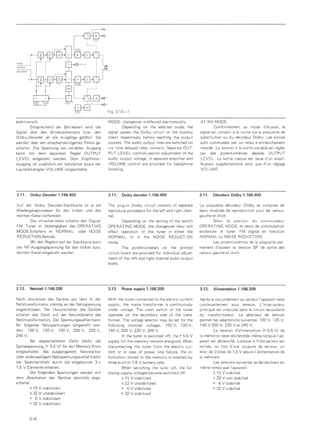
Entsprechend der Betriebsart wird das
Signal
uber den
Blindsteckeinsatz bzw. den
Dolby-Decoder
an die Ausgange
gefuhrt. Sie
werden uber
ein einschaltverzogertes Relais ge-
schaltet. Die Spannung
am
variablen Ausgang
kann mit dem
separatee
Regler
OUTPUT
LEVEL
eingesteilt
werden. Dem
Kopfhorer-
Ausgang ist zusatzlich ein Verstarker sowie
der
Lautstarkeregler
VOLUME
vorgeschaltet.
MODE, changeover is effected electronically.
-
Depending on the selected
mode,
the
signal passes the Dolby circuit or the
dummy
insert
respectively before reaching the output
sockets. The audio output lines
are
switched
on
via time delayed relay contacts. Separate
OUT-
PUT
LEVEL controls permit adjustment
of
the
audio
output
voltage.
A
separate amplifier and
VOLUME control are provided for headphone
listening.
ATING MODE.
Conformement
au mode d'ecoute, le
signal
est conduit
a
la sortie via
la
plaquette de
substitution ou du decodeur Dolby.
Les
sorties
sont commutees par un relais
a
enclenchement
retarde.
La
tension
a
la sortie variable
est
reglee
par des
potentiometres separes
OUTPUT
LEVEL. La sortie casque est issue d'un ampli-
ficateur supplementaire ainsi que d'un reglage
VOLUME.
3.11.
Dolby Decoder 1 .1
66.400
Auf der
Dolby Decoder-Steckkarte ist
je
ein
Wiedergabeprozessor fur den linken und den
rechten
Kanal
vorhanden.
Das Umschaltrelais schaltet den Digital-
FM Tuner
in
Abhangigkeit
des OPERATING
MODE-Schalters
in NORMAL-
Oder NOISE
REDUCTION-Betrieb.
Mit den Reglern auf der
Steckkarte kann
die
NF-Ausgangsspannung fur
den linken
bzw.
rechten
Kanal eingesteilt
werden.
3.1 1
.
Dolby
decoder 1
.1 66.400
The
plug-in Dolby
circuit consists
of
separate
reproduce processors for the
left and right chan-
nel.
Depending on the
setting of
the
switch
OPERATING MODE,
the changeover
relay
will
effect operation of the tuner in either the
NORMAL
or
in the NOISE
REDUCTION
mode.
The
potentiometers on the printed
circuit
board are provided for
individual adjust-
ment of
the left and
right
channel audio
output
levels.
3.1
1.
Decodeur
Dolby
1.166.400
La
plaquette
decodeur
Dolby se compose de
deux modules de reproduction pour les canaux
gauche
et
droit.
Selon la position du commutateur
OPERATING
MODE, le relais de commutation
enclenche le tuner FM digital en
fonction
NORMAL
ou
NOISE REDUCTION.
Les
potentiometres
de
la plaquette
per-
mettent d'ajuster la tension BF de
sortie des
canaux gauche et
droit.
3.12.
Netzteil 1.166.200
Nach Anstecken des Cerates
ans
Netz ist der
Netztransformator
standig
an der
Netzspannung
angeschlossen. Der
Hauptschalter des Cerates
schaltet
das Gerat auf der
Sekundarseite
des
Netztransformators.
Der Spannungswahler kann
fiir
folgende
Netzspannungen eingesteilt wer-
den:
100V, 120V, MOV,
200 V, 220V,
240
V.
Bei abgeschaltetem
Gerat bleibt die
Speisespannung
(+
5,6
V) fur den Memiory-Kreis
eingeschaltet.
Bei ausgezogenem Netzstecker
Oder anderweitigem
Netzspannungsausfall bleibt
der
Speicherinhalt
durch die eingebauten
3
x
1
,5 V
Elemente
erhalten.
Die
folgenden
Spannungen
werden mit
dem
Abschalten des
Cerates ebenfalls abge-
schaltet:
±
1
5 V
stabilisiert
±
22 V unstabilisiert
+
6 V stabilisiert
+
32 V stabilisiert
3.12.
Power
supply 1
.166.200
With the tuner connected
to
the electric current
supply, the mains transformer
is
continuously
under voltage. The main
switch
of
the
tuner
operates on the
secondary
side
of the trans-
former. The voltage
selector
may
be set for the
following
nominal voltages:
100
V,
120
V,
1 40
V,
200
V,
220
V,
240 V.
If
the tuner
is
switched off, the+
5.6 V
supply for the memory remains energized. When
disconnecting the tuner from the electric
cur-
rent
or in case of power line failure, the
in-
formation
stored in the memory is retained
by
three built-in 1
.5 V
battery cells.
When
switching the tuner off, the fol-
lowing
supply voltages become switched off:
±
1
5
V
stabilized
±
22 V unstabilized
+
6 V
stabilized
+
32 V
stabilized
3.12.
Alimentation
1.166.200
Apres le raccordement
au
secteur I'appareil reste
continuellement sous tension. L'interrupteur
principal est intercale dans
le
circuit secondaire
du transformateur.
Le
selecteur de tension
permet les
adaptations
suivantes: 100
V,
120
V,
140
V
200
V, 220 Vet 240 V.
La
tension
d'alimentation (+
5,6
V)
de
la memoire reste
enclenchee meme lorsque
I'ap-
pareil est declenche.
Lorsque la fiche secteur
est
retiree, ou lors
d'une coupure
de
secteur, un
bloc
de
3
piles
de
1
,5
V assure I'alimentation
de
la memoire.
Les tensions suivantes se
declenchent en
meme
temps que I'appareil:
±
1
5
V
stabilise
±
22 V non stabilise
+
6
V stabilise
+
32 V
stabilise
3-6
 Loading...