S]II'DtrR REVOX
PR99
REPRODUCE ONLY sEcrtoN 3/5
3.2.4
Frequenzgangkontrol le ab
Testband
1.
2.
Testband auf den Frequenzgangteil
vorspulen.
NF-Millivoltmeter
an
LINE
OUTPUT
(Cll1
und CH2) anschliessen.
1.
3. Gerät
auf
Wiedergabe
starten und
3.
den
Frequenzgang bezogen auf
1000H2 kontrollieren und den Hö-
henanteil
mit den Reglern
TREBL
E CH'1 u nd
'
CHZ
FAST
und SLOl,l
ei nstel I en.
3.2.4
Checking
of
frequency response with
test
tape
Advance test tape
to frequency
response
section.
2. Connect
AF-millivoltmeter to
LINE
OUTPUT
CH'l and CH2.
Start
machine in reproduce
mode and
check
frequency response
relative
to
1000H2.
Adjust the treble with
the
aid of the
potmeters
TREBLE
CH1 and
CH2 FAST and SLOW.
3.2.4
Contröle de
'la
rdponse en frdquence
par
bande test
1.
Amenez la bande test sur les
frd-
quences
de
r6fdrences.
Raccordez le millivoltmötre BF
ä la
sortie
LINE OUTPUT
(CHl
et
CH2)
Faites marcher 1'appareil en
lecture
et contrölez
'la
r6ponse en
frdquence
(r6f6rence
1000H2),
ajustez les
aigues
au moyen
des
potentiomötres
TREBLE CH1 et CH2
FAST
et
SL0L^J.
2.
))
Rdglage
des
potentiomötres
de l'inter-
face
E.0.M
(au
bas du magndtophone)
Avant-propos:
Les 169lages
suivants
ont 6td fait ä
l'usine. Ils sont ä contröler seul-
ment en
cas
de rdparation ou si
l'interface E.0.lvl. ne fonctionne
pas
pa
rfa
i
temen t ,
1.
Posez
une
bande
avec
le signal de
25Hz
au niveau opdrationnel
(du-
16e
environ
1min.).
2. Raccordez
un
mi
I I
i
vol tmötre BF aux
sorties OUTPUT
CH'l et CH2.
3. Pressez
la touche PLAY et ajustez
les
potentiomötres
BR CH1 et BR CH2
pour
1e niveau de
sortie
minimale.
4. Raccordez
le millivoltmötre BF ä
R45
ou ä l'IC3/pin
1 sur l'inter-
face
E.0.1'1.
1 .177 .960 .
Pressez
la touche PLAY. Ajustez
pour
1e niveau maximale
a I'aide
du
potentiomötre
BP
CH1.
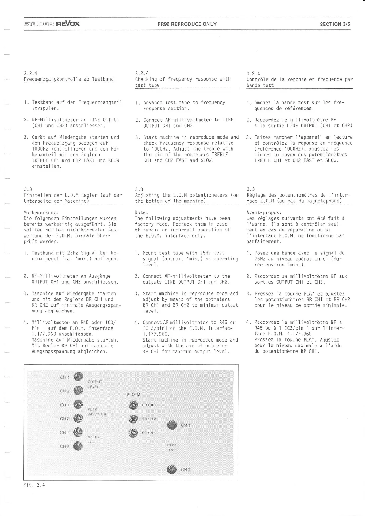
?2
Ei nstel I en
Untersei
te
E.0.M Regler
(auf
der
l4aschine)
Vorbemerkung:
Die folgenden Einstellungen wurden
bereits werkseitig ausgeführt. Sie
sollten nur bei nichtkorrekter
Aus-
wertung
der E.0.M. Signale über-
prüft
werden.
1.
Testband nit 25Hz Signal bei No-
minalpegel
(ca.
1min.
)
auflegen.
2. NF-Mi
I I
i
vol tmeter an
Ausgänge
0UTPUT CHi
und CH2
anschl iessen.
3. l4aschine auf !Jiedergabe starten
und
mit
den
Reglern BR CH1
und
BR
CH2 auf mjnimale Ausgangsspan-
nung abgleichen.
4. Millivoltmeter an R45 oder
IC3/
Pin'l
auf
dern
E.0.M. lnterface
1
.177
.960 anschl
i
essen.
Maschine
auf l^liedergabe
starten.
Mit Regler BP
CH1 auf maximale
Ausgangsspannung
abgl eichen.
Adjusting
the
E.0.M
potentiometers
(on
the
bottom
of the machine)
Note:
The fol Iowing adjustments have been
factory-made. Recheck them
in case
of
repair or incorrect operation of
the E.0.M.
interface on1y.
1.
Mount test
tape with 25Hz test
signal
(approx.
1min.
)
at operating
I
eve.l .
Connect
AF-mi I
I
i
vol tmeter
to the
outputs
LINE 0UTPUT CH1 and
CH2.
Start
mach'ine in reproduce mode and
adjust
by means of the
potmeters
BR CH1
and BR CH2 to minimum output
I
evel
.
ConnectAFmillivoltmeter
to
R45
or
i C 3/p
i n
1 on the E.0. M.
i nterface
1.177.960.
Start machine in reproduce
mode
and
adjust with the aid of
potmeter
BP CH1
for
maximum output
leve1.
x,
der
der
2.
)
**r
s
**"u,
*l.i ä
üt'r
1
üfi;
*r'{
1
w
{ffi
ffi
w
w
*$ *x
!,i,ll!{.:e?,Stt
€:#.
n4
ffi'
{ffi
w
l*R:**3:X
$?i3
,f
t{ 1
ffi
*x-
.f*qFs.
t"tiärF i,
S
**u*
Fig.3.4
 Loading...