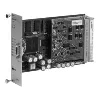
8/10 VT-HACD-DPQ | Digital control electronics
Bosch Rexroth AG, RE 30146, edition: 2013-10
Pin assignment of the male multipoint connector
Pin assignment of the D-Sub socket on the front panel
Pin Row z Row b Row d Row f
2 n.c. AI3+: Internal mold pressure
1)
DI1: Back pressure DO7: Pressure
4 n.c. AI3–: Internal mold pressure
1)
DI2: Auto SSI clock+
6 n.c. AI2+: Actual pressure value FB 1
1)
DI3: Start holding pressure SSI clock–
8 n.c. AI2–: Actual pressure value FB 1
1)
DI4: Injection/jog+ SSI data+; inc. Ua1
10 n.c. AI1+: Pressure command value
1) 3)
DI5: Incremental home SSI data–; inc. /Ua1
12 Shield AI1–: Pressure command value
1) 3)
DI6: Post-retraction/jog- Inc. Ua2
14 n.c. AI4+: Actual pressure value FB 2
1)
DI7: Analog injection /inc. Ua2
16 n.c. AI4–: Actual pressure value FB 2
1)
DI8: Analog command value Inc. Ua0
18 n.c.
AI5+: Analog cyl. position
1)
Enable /inc. Ua0
20 System earth
AI5–: Analog cyl. position
1)
DO1: Actual velocity profi le n.c.
22 DO3: Back pressure AI6+: Velocity command value
1)
Card OK. n.c.
24 DO4: Injection AI6–: Velocity command value
1)
Data+: Local bus
n.c.
26 DO5: Retraction completed AO3: Valve output DO2: Signal error n.c.
28 DO6: Injection position Analog GND
Data-: Local bus
CAN Gnd
30 UB: +24 V –10 V AO1: Valve output 1
2)
CAN L
32 LO: 0 V +10 V AO2: Valve output 2 CAN H
1)
By means of software, the inputs can be set to 0…10 V, ±10 V,
0…20 mA or 4…20 mA.
2)
By means of software, output AO1 can be set to 0…10 V, ±10 V
or 4…20 mA.
3)
This input has an input resistance of R
i
> 10 MΩ
n.c. ... not used in basic version, however reserved for extensions.
9
5
6
1
GND
Transmission data (RS232)
Reception data (RS232)
Card dimensions Euro-card 100 x 160 mm, DIN 41494
Front plate dimensions:
Height 3 HE (128.4 mm)
Width soldering side 1 TE (5.08 mm)
Width component side 7 TE
Admissible operating temperature range
0 to 50 °C
Storage temperature range
–20 to +70 °C
Weight m 0.2 kg
Technical data (continued)

 Loading...