4/25
(*) : only for Poland
(3) Figure for iso thermal conditio ns.
building, mounting height of the unit, ambient temperature & adjustment of the lo uvres.
(6) Sound pressure level in dB (A) in free field co nditio ns, measured at 5 metres fro m the unit
(7) Sound pressure level in dB(A), measured at 5 metres from the unit with A=160m² and Q=2
(5) Iso thermal co nditio ns at 20°C ambient air temperature, discharge louvre zero deflectio n, v = 0,5 m/s. The air throw will be influenced by the height o f the
(4) Height fro m floo r to bo ttom surface o f heater. These are reco mmandatio ns o nly. Po sitio ning o f unit heaters fo r pro per perfo rmance is applicatio n dependent.
Care sho uld be taken to avo id mounting the heaters above these recommendations, unless downturn nozzle optio ns are used, as significant stratification may
occur resulting in poo r flo o r coverage and higher energy losses thro ugh the ro of structure.
line to minimize the pressure drop thro ugh the gas pipes - if necessary, reduce the diameter of the supply line at the inlet of the unit.
(1) Gas A ppliance Classificatio ns for Aprroved Venting M ethods based o n CEN-report CR1749:2001
(2) There is a difference between the gas co nnectio n diameter and the diameter of the supply line. Always use the mo st adequate diameter o f the supply
TECHNICAL DATA
2.1 Specifications
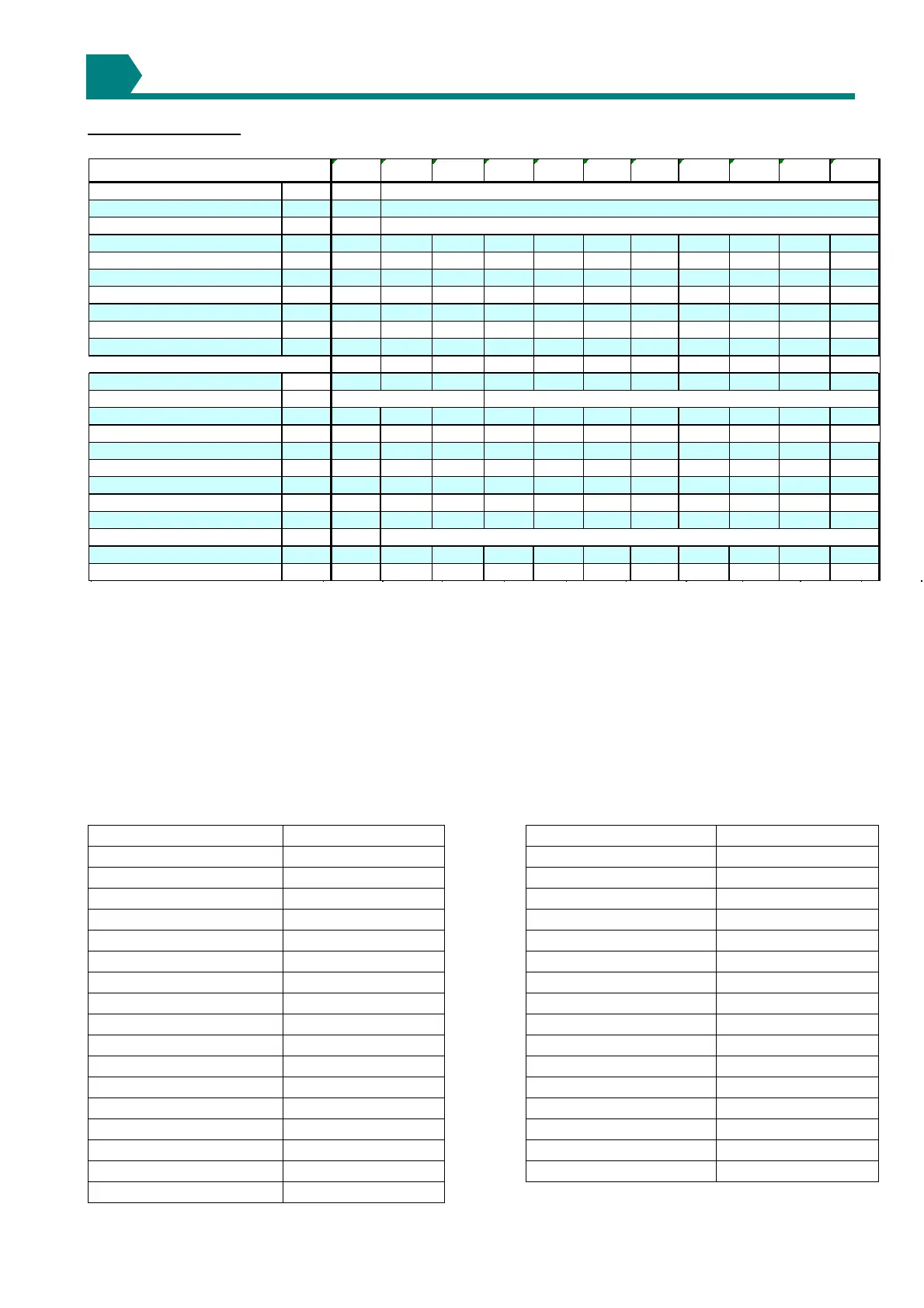
Table 1a
Table 1b : Gas categories
Country Gas category Country Gas category
Austria II2H3P Montenegro II2H3+
Belarus II2H3+ New Zealand II2H3+
Bulgaria I2H or I3P Norway II2H3 B/P
China II2H3+ Poland II2E3P
Czech republic II2H3+ Portugal II2H3+
Croatia II2H3P Romania II2H3 B/P
Cyprus II2H3+ Russian Federation I2H or I3P
Denmark II2H3 B/P Serbia II2H3+
England II2H3+ Slovakia II2H3+
Estonia II2H3+ Slovenia II2H3+
Finland II2H3 B/P South Africa II2H3+
Germany I2ELL Spain II2H3+
Greece II2H3+ Sweden II2H3 B/P
Hungary II2HS3P Turkey II2H3+
Iceland II2H3+ Ukraine I2H or I3P
Latvia II2H3+
Lithuania II2H3+
2
LCSA-4 12 20 30 35 45 50 60 75 100 120 145
Gas category
Comb. Air & Flue, type B
(1)
Comb. Air & Flue, type C
(1)
Connection collars mm 80 100 100 130 130 130 130 130 130 130 130
Heat input Hs kW 13,33 26,42 31,63 43,95 54,38 61,08 73,25 87,85 114,87 144,81 165,47
Heat input Hi kW 12,00 23,80 28,50 39,60 49,00 55,00 66,00 79,15 103,50 130,40 149,00
Heat output kW 11,14 21,82 25,99 36,23 44,64 50,77 60,92 73,13 94,50 119,32 137,39
Thermal Efficiency % 93,00 92,00 91,00 92,00 91,00 92,00 92,00 92,00 91,00 92,00 92,00
m³/h 1,27 2,52 3,02 4,19 5,19 5,82 6,98 8,38 10,95 13,80 15,77
kg/h NA 1,86 2,22 3,09 3,82 4,29 5,15 6,17 8,24 10,17 11,62
Gas consumption Lw (20mbar)
(*)
m³/h NA 3,07 3,68 5,11 6,32 7,10 NA 10,22 NA NA NA
m³/h NA 3,50 4,19 5,82 7,20 8,08 NA 11,63 NA NA NA
Gas pipe connection
(2)
Real temperature rise
(3)
K 30 31 33 33 31303429 29 32 35
Air flow measured
(3)
m³/h 1100 2000 2300 3200 4300 5000 5200 7300 8000 10800 11400
Nominal motor speed RPM 1381 1256 1333 1300 1310 928 1346 1344 935 872 875
Recommended mounting height
(4)
m2,5
3 444455566
Horizontal throw
(5)
m9,5
13 17 24 25 27 30 32 31 38 39
Sound Pressure
(6)
dB(A) 36
42 37 46 45 45 47 48 52 54 56
Sound Pressure
(7)
dB(A) 43
49 44 53 52 52 54 55 59 61 63
Electrical service (protection IP20)
Total electrical rating W 530
360 250 370 370 540 760 760 850 1730 1730
Weight kg 59
59 64 94 99 114 114 126 184 242 279
see table 1B
B22P
C12, C42, C62
Gas consumption G31
Gas consumption G20
230/240V 1N ~ 50Hz
1/2"
Gas consumption Ls (13mbar)
(*)
3/4"