Form I-ADF, Page 10
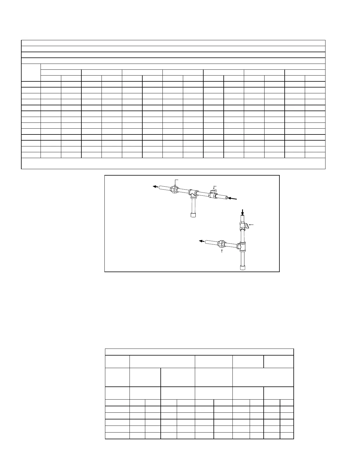
FIGURE 6 - Gas Supply
Connection
Gas Supply Piping
Supply Pressure
These direct-red makeup air systems are designed to operate on a natural gas
supply pressure range of a minimum of 6" w.c. to a maximum of 28" w.c. If the natural
gas supply pressure is above the maximum allowed, it is necessary to install a eld-
supplied step-down gas regulator in the supply line. Order and install the appropriate
Gas Regulator Kit, Option CZ1 (1") or CZ2 (1-1/2"). Follow the instructions provided
with the kit. Measure the gas pressure between the step-down regulator and the unit.
Maximum Supply Pressure by Manifold
Manifold Option BM75, BM76 - 1/2 psi
Manifold Option BM78, BM79 - 2 psi
6.0 Mechanical
(cont'd)
6.1 Gas Piping and Pressures (cont'd)
Capacity of Piping
Cubic Feet per Hour based on 0.3" w.c. Pressure Drop
Specic Gravity for Natural Gas -- 0.6 (Natural Gas -- 1000 BTU/Cubic Ft)
Specic Gravity for Propane Gas -- 1.6 (Propane Gas -- 2550 BTU/Cubic Ft)
Length
of Pipe
Diameter of Pipe
3/4" 1" 1-1/4" 1-1/2" 2" 2-1/2" 3"
Natural Propane Natural Propane Natural Propane Natural Propane Natural Propane Natural Propane Natural Propane
20' 190 116 350 214 730 445 1100 671 2100 1281 3300 2013 5900 3599
30' 152 93 285 174 590 360 890 543 1650 1007 2700 1647 4700 2867
40' 130 79 245 149 500 305 760 464 1450 885 2300 1403 4100 2501
50' 115 70 215 131 440 268 670 409 1270 775 2000 1220 3600 2196
60' 105 64 195 119 400 244 610 372 1105 674 1850 1129 3250 1983
70' 96 59 180 110 370 226 560 342 1050 641 1700 1037 3000 1830
80' 90 55 170 104 350 214 530 323 990 604 1600 976 2800 1708
90' 84 51 160 98 320 195 490 299 930 567 1500 915 2600 1586
100' 79 48 150 92 305 186 460 281 870 531 1400 854 2500 1525
125' 72 44 130 79 275 168 410 250 780 476 1250 763 2200 1342
150' 64 39 120 73 250 153 380 232 710 433 1130 689 2000 1220
175' 59 36 110 67 225 137 350 214 650 397 1050 641 1850 1129
200' 55 34 100 61 210 128 320 195 610 372 980 598 1700 1037
Note: When sizing supply lines, consider possibilities of future expansion and increased requirements. Refer to National Fuel Gas Code for additional
information on line sizing.
*See gas
connection
location in
FIGURE 1A
or 1B.
Minimum Supply Gas Pressure for Full Fire
Manifold
Option
BM75 BM76 BM78 BM79
with Gas
Control
Option
AG1 AG3
AG 30, 31,
32, 33, 35, 36,
or 37
AG 30, 31, 32, 33, 35,
36, or 37
Manifold
Size
1" 1" 1" 1" 1-1/4"
MBH Nat Pro Nat Pro Nat Pro Nat Pro Nat Pro
250 4.0 1.4 4.0 N/A 4.1 1.6 4.4 1.6 4.6 1.6
500 5.3 1.9 5.0 N/A 5.8 2.3 6.0 2.3 5.2 1.9
750 7.5 2.7 6.8 N/A 8.5 3.3 8.4 3.3 6.1 2.3
1000 -- -- -- -- 12.4 4.7 11.7 4.6 7.4 2.8
1250 -- -- -- -- -- -- -- -- 9.1 3.5

 Loading...


