Form I-ADF, Page 20
The optional remote console is shipped separately. Remote consoles include terminal
blocks for wiring. If ordered with a remote console, the toggle switch is mounted on
the console and depending on what gas control option was ordered, the console could
include a temperature selector. If a dirty lter switch is ordered the indicator light is on
the console. See FIGURE 22 for console size.
Remote Console
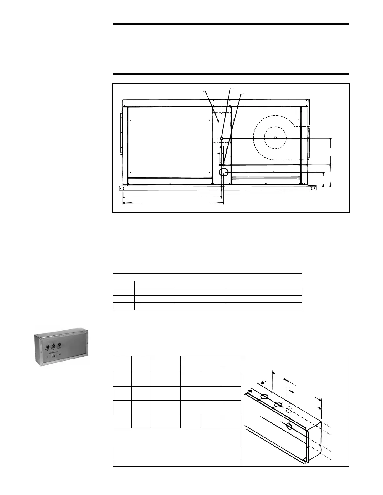
FIGURE 21- Disconnect
Switch Location and
Wiring Connection
Locations (Model ADF
is illustrated; same
dimensions/locations
apply to Model ADFH)
CAUTION: Supply voltage and 24-volt control wiring cannot be
installed in the same conduit. Maxitrol systems will be adversely
affected if control wiring is in conduit with supply voltage wiring. If
required, eld-supplied wiring between any Maxitrol components
must be completed with shielded wiring.
7.3 Control Wiring
Refer to FIGURE 21 for location of control wiring connection. Low voltage wiring must
be in individual conduit, separated from primary high voltage wiring.
A 3-position control switch is supplied with each system, either packed loose inside the
unit, or if an optional control console is ordered, the switch is mounted on the console.
Control wiring requirements depend on the options selected. Follow the custom wiring
diagram supplied with the system to connect any remote controls. For additional
reference, the control manufacturer's instructions are included in the owner's envelope.
Control Wiring Maximum Lengths - ft (M)
Volts Wire Gauge Total Wire Length Distance from Unit to Control
24 18 150 (45.7) 75 (22.9)
24 16 250 (76.2) 125 (38.1)
24 14 350 (106.7) 175 (53.3)
Control
Switch
Qty of
Lights*
Temperature
Selector**
Dimensions - inches (mm)
L**** H**** D
Yes 3 Yes
10-3/4
(273)
7-5/8
(194)
2-5/8
(67)
Yes 3 No
10-3/4
(273)
7-5/8
(194)
2-5/8
(67)
Yes 4 Yes
15-3/4
(400)
7-5/8
(194)
2-5/8
(67)
Yes 4 No
15-3/4
(400)
7-5/8
(194)
2-5/8
(67)
* 3 - Blower On, Burner On, and Safety Lockout on both
RC13 and RC14; 4th light is Dirty Filter Indicator on
Option RC14 only
** On the console with Gas Control Options AG 31, 32,
33, or 35
**** Subtract 1" (16mm) when recessing
Locations of Knockout Holes
(dimensions to
centerlines
of holes)
FIGURE 22 - Remote
Console Dimensions
(Dimensions, components,
and wiring required depend
on options selected; refer
to the wiring diagram to
identify options.)
7.0 Electrical and
Wiring (cont'd)
7.2 Supply Wiring
(cont'd)

 Loading...


