Form I-ADF, P/N 131805 R6, Page 21
When a console with a dirty lter indicator is selected, the remote console includes a
fourth light (dirty lter indicator light). The light is activated by an adjustable, single-
pole/normally open differential pressure switch that senses air pressure across the lter
bank. There are eld-installation procedures that must be done for proper operation of
the dirty lter indicator light.
Dirty Filter Switch Installation Instructions
Before the system is operating, connect the sensing tubes from the switch to
their sensing locations in the eld-installed lter cabinet.
1) Run the tubes through the holes in the cabinet wall. Pull gently to extend the
tubing to its entire length without stress.
2) Position the tubing approximately at the center of the height of the lter rack.
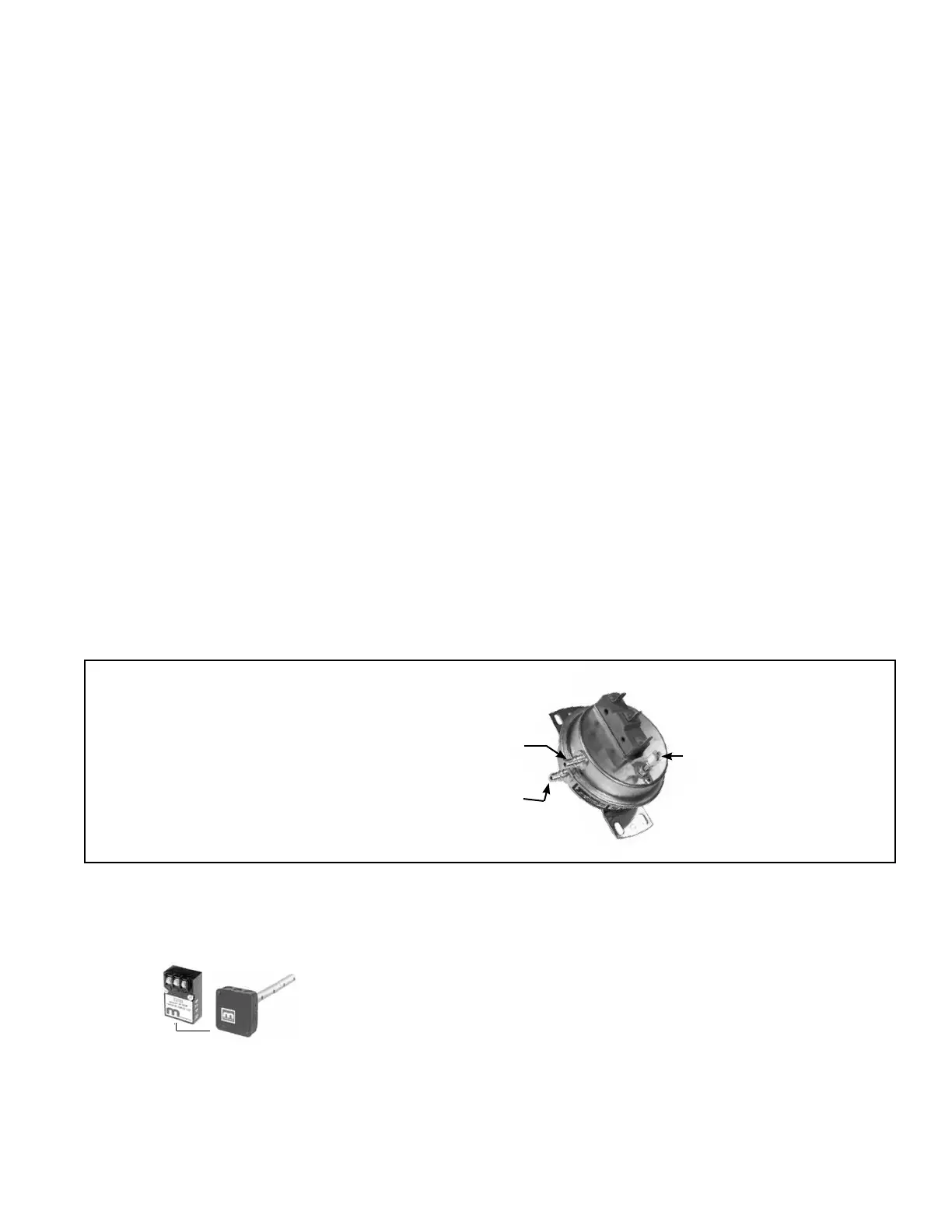
3) Identify the tube connected to the positive connection on the switch (FIGURE
23) as the positive pressure tube. Determine the length of tubing required to
attach the positive pressure tube so that it will sense pressure at the inlet
side of the lter rack.
Identify the tube connected to the negative connection on the switch (FIGURE
23) as the negative pressure tube. Determine the length of tubing required to
attach the negative pressure tube so that it will sense the pressure at the
blower side of the lter rack.
(NOTE: Tubing shipped is the same length for all sizes of systems; cut to the
appropriate length for the smaller systems.)
4) If required, cut the tubing to the proper lengths. Using the clamps provided,
attach the ends of the tubing to the lter rack at about center height being
careful not to kink or compress the tubing.
After the system is operating, the lter switch must be manually set. With
clean lters in place, blower doors closed, and blower in operation, increase the
pressure setting by adjusting the set screw on the switch clockwise until the lter
light is energized or the screw is bottomed out. At that point, adjust the set screw
three full turns counterclockwise or until the screw is top ended. At that setpoint,
the lter light will be activated at approximately 50% lter blockage.
Dirty Filter Light
(on the Remote
Console)
FIGURE 23 -
Dirty Filter
Pressure Switch
Set screw (on front
of switch) must be
manually adjusted after
system is in operation.
Negative pressure connection
is toward the "front or top" of
the switch (senses blower side
of lters)
Positive pressure connection is toward the
"back or bottom" of the switch (senses air
inlet side of lters)
Discharge Temperature Sensor (Maxitrol) for Gas Control Options AG30,
AG31, AG32, AG33, and AG36
A discharge sensor may be shipped separately for eld installation. Attach the discharge
sensor and mixing tube in the ductwork about six feet (1.8 M) from the discharge
opening of the system.
The sensor housing is not waterproof. If the installation is outdoors, eld-fabricate a
waterproof protective enclosure for the discharge sensor, being careful not to affect its
air temperature sensing capability.
Refer to the wiring diagram and connect the sensor to the terminal strip in the blower
section electrical box. Use shielded wire to alleviate any electrical interference that my
cause an erroneous discharge temperature reading.
Outside Air Cutoff Control (Option BN2)
After sensing pilot ame, the burner ignites at its lowest input rate. The "amount
of heat" required to reach the desired discharge temperature also depends on the
Discharge
Sensor
and
Mixing
Tube
8.0 Controls

 Loading...


