Form I-ADF, P/N 131805 R6, Page 9
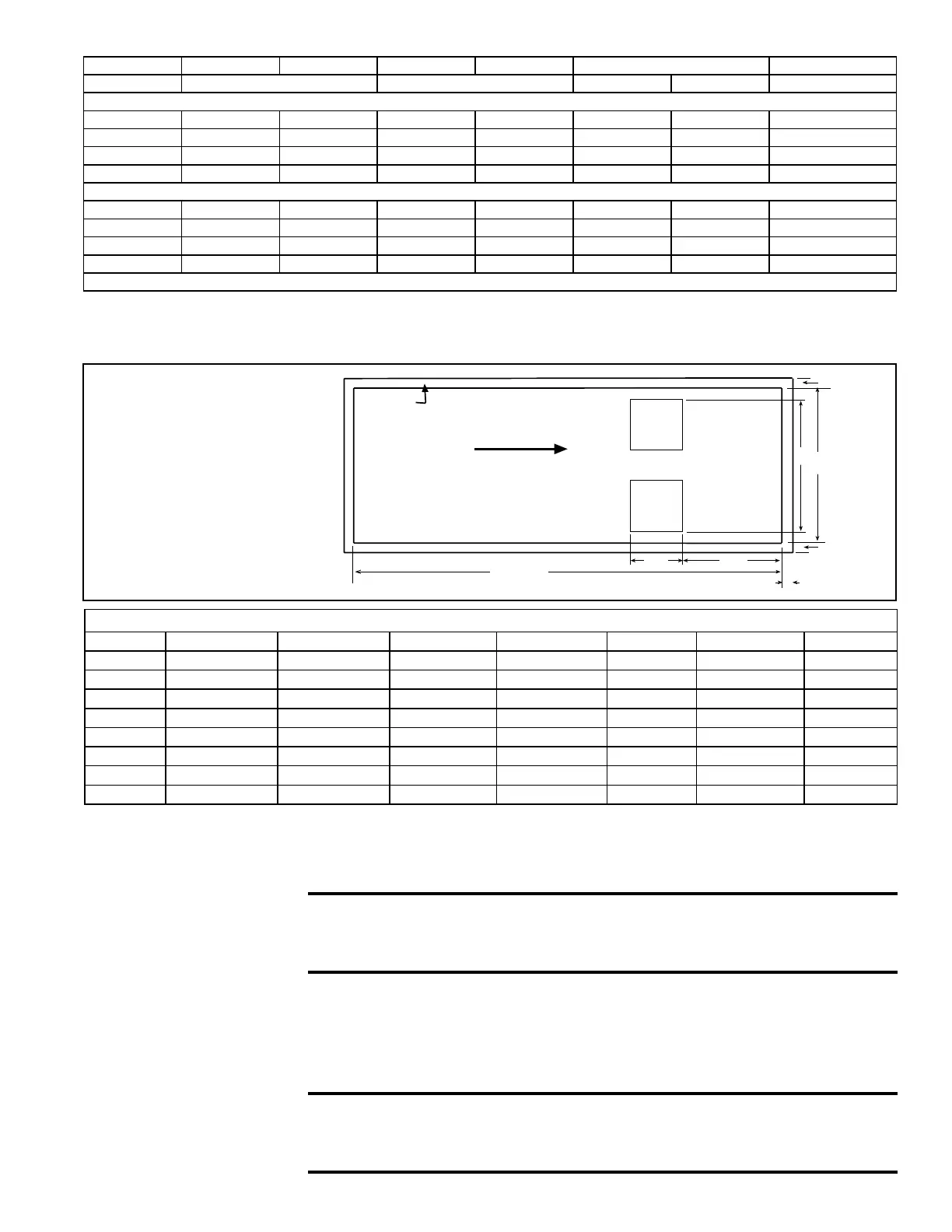
FIGURE 5 - Vertical Duct
Connection in Relationship
to Reznor
®
Roof Curb
Bottom (Vertical) Duct
Connections
If the system being installed has a vertical discharge, the duct opening has anges for
connection to eld-installed ductwork. See FIGURE 5 for duct opening and spacing in
relationship to currently manufactured Reznor
®
roof curbs.
Model ADF300 ADF500 ADFH300 ADFH500 ADF700/1200 ADFH700/1200
Discharge Horizontal or Vertical Vertical Only Horizontal Vertical Vertical Only
Roof Curb Dimensions (inches) - FIGURE 4
A 84-9/16 84-9/16 108-1/4 108-1/4 90-7/8 115-25/32 115-25/32
B 29-13/16 43-9/16 29-13/16 43-9/16 54-1/2 54-1/2 54-1/2
C* 80-13/16 80-13/16 104-1/2 104-1/2 87-1/8 112-1/32 112-1/32
D* 26-1/16 39-13/16 26-1/16 39-13/16 50-13/16 50-13/16 50-13/16
Roof Curb Dimensions (mm) - FIGURE 4
A 2148 2148 2750 2750 2308 2941 2941
B 757 1106 757 1106 1384 1384 1384
C* 2053 2053 2654 2654 2213 2846 2846
D* 662 1011 662 1011 1291 1291 1291
*C and D are roof opening dimensions.
Dimensions - inches (mm)
Model A B C D E F G
ADF300 80-13/16 (2053) 26-1/16 (662) 4-25/32 (121) 13-13/16 (351) 5-5/8 (143) 15-15/16 (405) 4-1/2 (114)
ADF500 80-13/16 (2053) 39-13/16 (935) 4-25/32 (121) 16-1/16 (408) 19-1/4 (489) 14-13/16 (376) 5-3/4 (146)
ADF700 112-1/32 (2846) 50-13/16 (1291) 28-19/32 (726) 13-13/16 (351) 5-5/16 (135) 40-5/16 (1024) 5-5/16 (135)
ADF1200 112-1/32 (2846) 50-13/16 (1291) 28-19/32 (726) 16-1/16 (408) 5-5/16 (135) 40-5/16 (1024) 5-5/16 (135)
ADFH300 104-1/2 (2654) 26-1/16 (662) 28-19/32 (726) 13-13/16 (351) 5-5/8 (143) 15-15/16 (405) 4-1/2 (114)
ADFH500 104-1/2 (2654) 39-13/16 (935) 28-19/32 (726) 16-1/16 (408) 19-1/4 (489) 14-13/16 (376) 5-3/4 (146)
ADFH700 112-1/32 (2846) 50-13/16 (1291) 28-19/32 (726) 13-13/16 (351) 5-5/16 (135) 40-5/16 (1024) 5-5/16 (135)
ADFH1200 112-1/32 (2846) 50-13/16 (1291) 28-19/32 (726) 16-1/16 (408) 5-5/16 (135) 40-5/16 (1024) 5-5/16 (135)
6.0 Mechanical
6.1 Gas Piping and Pressures
All piping must be in accordance with the requirements of the National Fuel Gas Code
ANSI/Z223.1 (latest edition ). Gas supply piping installation must conform with good
practice and with all local codes.
High pressure testing of supply lines is acceptable, provided the
supply line has been disconnected from the unit and the pipe end
is capped. See Hazard Levels, page 2.
Read this section of the installation manual to determine the minimum gas supply
pressure required to provide a maximum gas capacity. Minimum gas supply pressure is
also stated on the heater rating plate. The heater manifold terminates at the gas supply
connection with a black iron pipe union. See FIGURE 6. Local codes may require a 6"
condensate trap. Gas connection is either 1", 1-1/4", or 2" depending on the size of the
system.
WARNING: All components of the gas supply system must be leak
tested prior to placing equipment in service. NEVER TEST FOR
LEAKS WITH AN OPEN FLAME.

 Loading...


