Form I-ADF, P/N 131805 R6, Page 19
Motor Pulleys and Blower Speed - Units are set at the factory for the RPM required
to meet the CFM and external static pressure specied on the order. If the estimated
external static is incorrect, or changes are made to the duct system, the blower RPM
may have to be changed. Motors are equipped with adjustable pitch pulleys which
permit adjustment of blower speed. Instructions are included in Paragraph 9.2, Startup,
for adjusting blower speed.
Blower Rotation - Each blower housing is marked for proper rotation. Checking blower
rotation is included in Startup, Paragraph 9.2
Motor Loads - Use an ammeter to check motor amps. Amps may be adjusted
downward by reducing blower RPM or by increasing duct system static pressure. The
open motor amp chart below can be used for sizing line wiring. For accurate amps,
read the motor manufacturer's rating plate; amps will vary depending upon type of
motor and motor manufacturer.
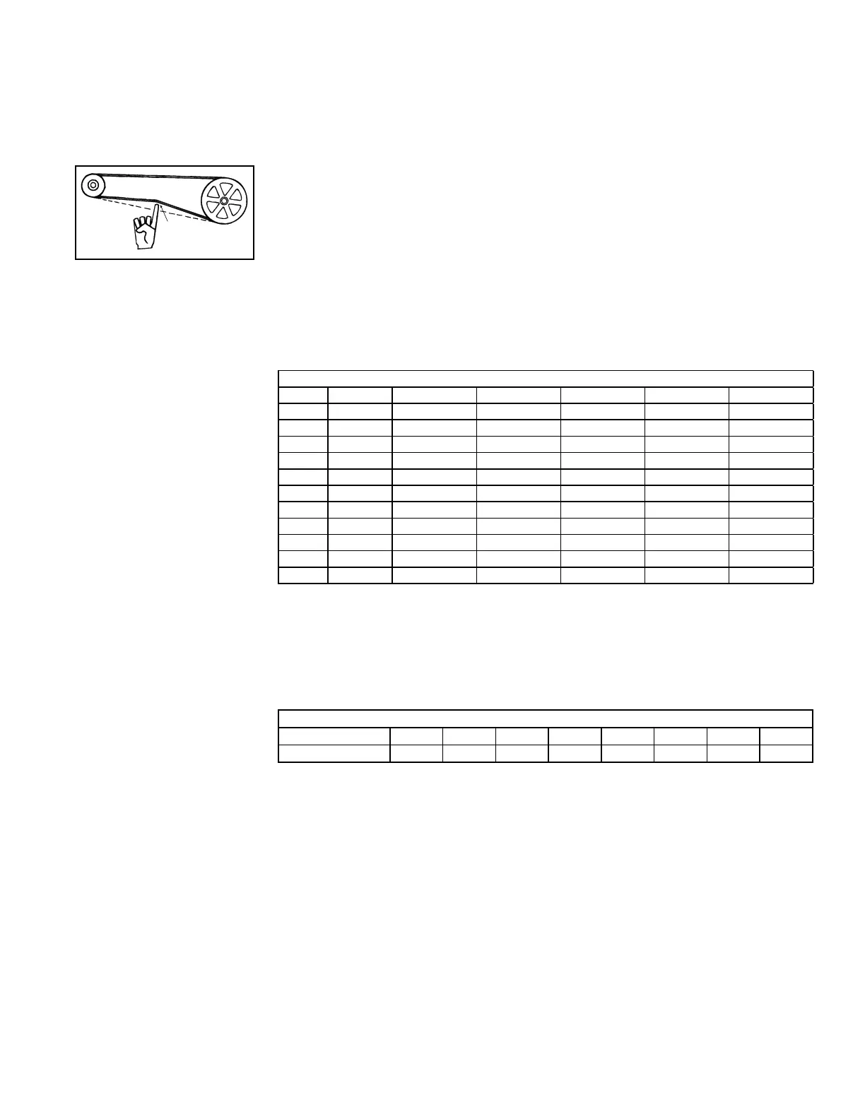
FIGURE 20 - Belt
Tension
6.4 Blowers, Drives,
and Blower
Motors
Check belt tension. Proper belt tension is important to the long life of the belt and motor.
A loose belt will cause wear and slippage. Too much tension will cause excessive
motor and blower bearing wear. If adjustment is required, adjust belt tension by means
of the adjusting screw on the motor base until the belt can be depressed 1/2" or 3/4"
(FIGURE 20). Be sure the belt is aligned in the pulleys.
Blower Motor Full Load Amps (open motors)
HP 115/1 230/1 208/3 230/3 460/3 575/3
1/2 8.8 4.4 2.1 2 1 --
3/4 11 5.5 2.9 2.6 1.3 --
1 13 7.5 3.7 3.2 1.6 1.4
1-1/2 15 7.5 5.6 5 2.7 2
2 N/A N/A 7 6.6 3.3 2.4
3 N/A N/A 9.1 8.4 4.2 3.6
5 N/A N/A 13.4 13.2 6.6 5.4
7-1/2 N/A N/A 22 21 10.5 8.4
10 N/A N/A 30 26 13 10.4
15 N/A N/A 43.1 39 19.5 16
20 N/A N/A 58.7 53 26.5 21.2
7.0 Electrical and
Wiring
7.1 General
All electrical wiring and connections including electrical grounding MUST be completed
in accordance with local, state and national codes and regulations and with the
National Electric Code (ANSI/NFPA 70) or in Canada the Canadian Electrical Code
Part 1 C.S.A. C.22.1.
7.2 Supply Wiring
Wire Gauge Sizes - 100 ft maximum
FLA 5 10 15 20 25 30 35 40
Wire Gauge 14 14 12 10 8 8 6 6
Run a separate line voltage supply directly from the building electrical panel to the
disconnect switch for the system. All external wiring must be within approved conduit
and have a minimum temperature rise rating of 60°C. For motor load amps, check the
motor nameplate.
Specic wiring diagrams and complete instructions are packed with each unit and
should be kept readily accessible in legible condition.
Disconnect Switch - A safety disconnect is required. An outdoor installation requires
a weatherproof disconnect switch. Install either an optional UL-listed disconnect or a
eld-supplied equivalent. Install the disconnect switch in accordance with Article 430 of
the National Electrical Code ANSI/NFPA 70 or in accordance with Canadian Electrical
Code Part 1-C.S.A. Standard C22.1. When attaching the disconnect switch to the
heater, use hardware with "teeth" to provide electrical grounding. The "teeth" should
face the disconnect switch, scratching off the painted surface. Attach the disconnect
tightly against the heater cabinet. (Refer to FIGURE 21.)
When providing or replacing fuses in a fusible disconnect switch, use dual element
time delay fuses and size 1.25 times the maximum total input amp as stated on the unit
rating plate.

 Loading...


