0108MLOOGBEN
12
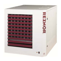
Figure 8 FLUE GAS FAN (venter) COMPONENTS
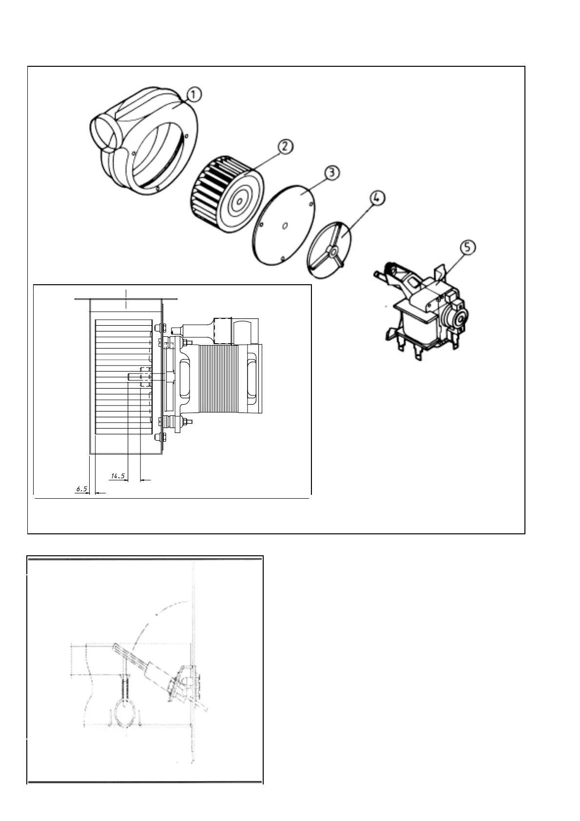
Figure 9 IGNITER ASSEMBLY DETAIL
8.8 To renew the motor capacitor. Fig.10 key 24.
This is located behind the motor end plate, access
is by removal of two screws. The capacitor is
secured in a spring clip and wire connection is by
1/4 "Faston" electrical connectors.
N.B. : ensure the "milor plastic" insulation ring fitted
inside the motor terminal housing is correctly
relocated should this become dislodged whilst
changing the capacitor and ensure the capacitor end
bolt touches the motor terminal housing thus
ensuring the capacitor electrical terminals do not
touch the opposite side of the motor housing.
8.9 To service the combustion air fan ("Venter") Fig.10
key 3 and Fig.8
A) Disconnect wires at the fan motor .fig.10 key
4.
B) Unscrew Qty. 3 cross head screws securing
motor and mounting plate to venter scroll.
Legend :
1. Fan housing
1. Impeller
1. Motor mounting
plate
1. Heat sink rotor
1. Motor
Fan impeller critaical
dimensions
 Loading...