Form CP-OPT-GMK (6-16), P/N 208831 R3, Page 3
3. Install the replacement ue duct & damper assembly with gear motor:
a. Using the new ue outlet duct gasket from the kit and the restrictor plate
removed in Step 2d, attach the new ue duct and combustion air damper with
gear motor assembly to the heater.
Model SC Series heaters - On the side of the ue duct in the new assembly,
remove the patch plate to attach the sensing probe removed in Step 2d. Slide
the long sensing tube through the hole and position it so that the tube will
extend into the round venter opening on the side of the ue duct. Use the
screws that had held the patch plate to attach the sensing tube plate to the ue
duct. Slide the rubber tubing (attached to the pressure switch) over the metal
tubing on the side of the ue duct. Be sure tubing is secure.
b. Using the new cover plate gasket, attach the ue duct cover plate removed in
Step 2c to the front of the newly installed ue duct and combustion air damper
assembly.
c. Using the new venter seal gasket and orice plate removed with the venter
housing, re-install the venter housing. Carefully re-attach the venter motor and
wheel assembly.
Model RP Series heaters - Slide the rubber tubing (attached to the pressure switch)
onto the sensing probe on the venter housing. Be sure that the tubing is secure.
d. Connect the wires. (Refer to the Replacement Gear Motor Diagram on page 4;
FIGURE 1 on page 1 & FIGURE 3 on this page):
• Connect the yellow wire from heater control compartment Terminal 87 to the
common terminal of the new combustion damper upper-end switch.
• Connect the orange wire from the heater control compartment Terminal 84 to
the common terminal of the new combustion air damper lower end-switch.
• Connect the purple wire from the normally-open terminal of the new
combustion air damper upper end-switch to Terminal 88 in the heater control
compartment.
• Connect the black wire from the normally-open terminal of the new
combustion air damper lower end-switch to Terminal 88 in the heater control
compartment.
• Connect the brown wire from the motor run time delay relay to Terminal 7 in
the heater control compartment.
4. Check Operation:
a. Turn on the electric and the gas.
b. Set the system control to “call” for heat.
c. Vary the control settings and observe for proper opening and closing of the
damper. The gear motor was factory set to fully close the damper and to open it
with approximately 1-1/8” (29mm) between the upper edge of the damper and
the duct assembly. If the damper door does not fully close or open properly,
loosen the adjusting screws as shown in FIGURE 4 and slide the end-switch
back and forth until proper operation is obtained. If necessary, carefully bend the
metal blade (FIGURE 5).
d. After it is determined that the newly installed combustion air damper is operating
correctly, replace the access panels. Check for proper operation of the heater.
Keep the Field Replacement Gear Motor Wiring on page 4 with the
original heater wiring diagram.
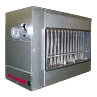
Lower End-Switch
Upper End-Switch
FIGURE 3
Side view of Flue Duct
Assembly showing
Combustion Damper
End-Switches
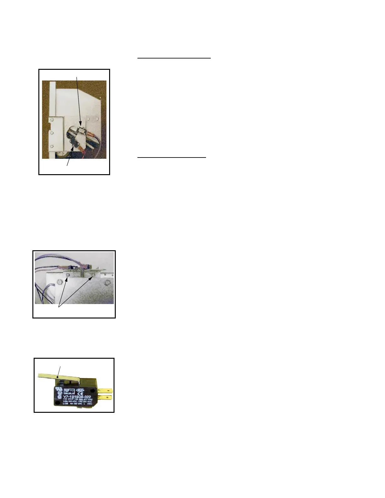
FIGURE 4
Top view of Combustion
Damper End-Switches
showing Damper
Adjustment Screws
Loosen screws and slide
End-Switch to adjust damper
FIGURE 5
End-Switch
Metal Blade
 Loading...