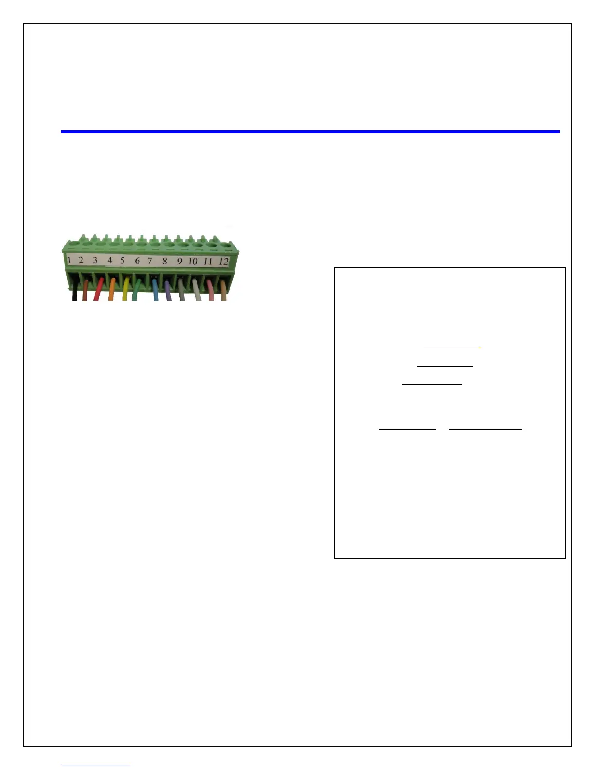
Pin Color How Used Where Used
1 = BLACK Motor -Azimuth
2 = BROWN Motor +Azimuth
3 = RED Motor -Elevation
4 = ORANGE Motor +Elevation
5 = YELLOW Motor - Skew
6 = GREEN Motor +Skew
7 = BLUE Count Azimuth
8 = VIOLET Count Elevation
9 = GRAY Count Skew
10 = WHITE Ground
11 = PINK 12 Volts DC GPS
12 = TAN GPS TXD GPS
After removing the appropriate wires from the 12 Pin Green
Connector, touch the following wires from the control cable directly
to any +/- 12 VDC source, such as the 12-volt source located at the
back of the controller or a drill battery. This will result in movement
of the antenna. To reverse the direction, reverse the wires (+/-) on
your battery.
• ELEVATION Red and Orange will raise and lower the
antenna.
• AZIMUTH Black and Brown will rotate the mount on
its base clockwise or counterclockwise
• SKEW Yellow and Green will tilt dish to the right or
left.
Wire Color Wire Function
BLACK +AZIMUTH
BROWN -AZIMUTH
RED +ELVATION
ORANGE -ELVATION
YELLOW - SKEW
GREEN +SKEW
 Loading...