workpiece at all times for proper cutting If the teeth of t
Blade are so far apart that they straddle the work, sever
damage to the workpiece and to the Made can result .
G.CHANGING BLADE:
Raise saw head to vertical position and open the blade
guards. Loosen tension screw knob sufficiently to allow
the saw blade to slip off the wheels. Install the new blad
with teeth slanting toward
he
e
e
the motor as follows:
blade upward with the right hand
m pulley and place is at
n
st
inger as guides.
(
H.
(1) (
(a)
) The position of the vise when tightened.
) The position of the vise when loosened.
ened.
as follows:
) Rise the arm 2” above the workpiece, close the
he arm 2” above the
ble. Move the vise
alf
e jaw bracket against the
w
h
h ce in
3) , hold the
) to a 90 degree
(c pened). Remove workpiece.
Whe
the e (a) to loosen and adjust workpiece
ndle to
(b)
e
e by turning rectangular handle only.
ten the
ar vise to the threaded hole position. (E)
). Set the scale to the desired angle.
)
11. BLADE GUIDE BEARING ADJUSTMENT
ATTENTION: This is the most important adjustment on
your saw. It is impossible to get satisfactory work from
your saw if the blade guides are not properly adjusted.
ting Band
(1). Place the blade in between each of the guide
bearings.
(2). Slip the blade around the motor pulley (bottom) with
the left hand and hold inposition.
(3). Hold the blade taut against the motor pulley by
pulling the
which is placed at the top of the Made.
(4). Remove left hand from botto
the top aide of the Made to continue the application o
the upward pull on theblade.
(5). Remove right hand from blade and adju
the position of the top pulley to permit left
hand to slip the blade around the pulley using
the thumb, index and little f
(6). Adjust the blade tension knob clockwise
until it is just right enough so no blade
slippage occurs. Do not tighten excessively.
7). Replace the blade guards.
(8). Place 2-3 drops of oil on the blade.
USAGE OF THE OUICK VISE:
2)
(b)
(3)
(1
(2
(Completely opened).
(3) The position of the vise when loos
( Half opened).
TRU-LOCK VISE SYSTEM
INSTRUCTIONS
To operate, proceed
1
cylinder valve to maintain t
workpiece.
2) Put your workpiece on the ta
handle (a) upwards to an angle of 45 degree (a-H
opened) to loosen the vise.
Move the vis
orkpiece by turning the rectangular
andle (b) . Push down on the vise
andle (a) to lock the workpie
position.
To loosen the workpiece from the vise
workpiece and lift the vise handle (a
position
ompletely o
CONTINUED CUTTING
n you need to cut a workpiece many times, just raise
vise handl
position. Then push down on the same ha
tighten.
You can also push the vise handle (a) down first, then
tightening the vise by turning the rectangular handle
clockwise. After finishing the cut, you can loosen th
workpiec
This Tru-Lock Vise System has a 3mm tightening travel
when the rectangular handle is completely opened.
There is only a 1mm tightening travel necessary for
normal metal materials. The operator can tigh
workpiece by pushing down the vise handle (a) with a
certain amount of pressure depending on hardness of
workpiece.
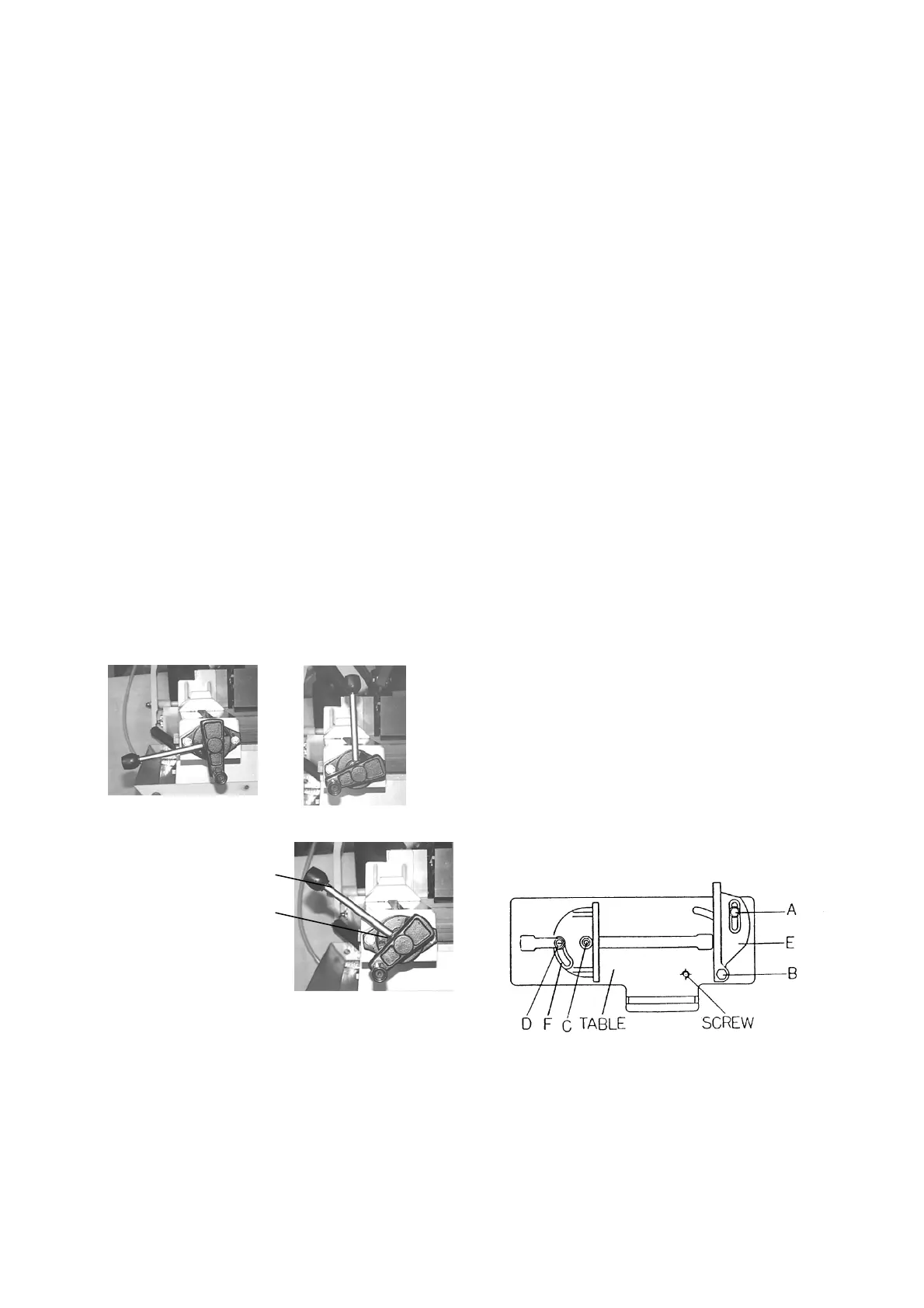
I. QUICK VISE ADJUSTMENT FOR ANGLE CUT:
(1). Loosen the A. B. C. D. Screw.
(2). Adjust re
(3
(4). Adjust the front vise (F) to parallel the rear vise(E
(5). Tighten the A. B. C. D. Screw.
The blade guide bearings on your metal. Cut
Saw are adjusted and power tested with several test cuts
before leaving the factory to insure proper setting The
-9-
 Loading...