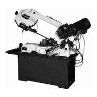
8. BI-METAL SPEEDS AND FEEDS
These figures are a guide to cutting 4"(100mm) material
(with a 314 Vari-Tooth) when using a cutting fluid.
Increase Band Speed: 15% When cutting
1/4"(6.4mm) material (l0/l4 Vari-Tooth)
12% When cutting 3/4"(19
mm) material (6/10 Vari-Tooth)
10% When cutting
1-1/4"(32 mm) material(5/8 Vari-Tooth)
5% When cutting 2-1/2"
(64 mm) material(4/6 Vari-Tooth)
Decrease Band Speed: 12% When cutting 8"(200mm)
material(2/3 Vari-Tooth)
BAND SPEED
MATERIAL ALLOY
ASTM NO.
FT./MIN M/MIN
173,932 314 96
330,365 284 87
623,624 264 81
230,260,272 244 74
280,264,632,655 244 74
101,102,110,122
,172
234 71
1751,182,220,51
0
234 71
625,706,715,934 234 71
630 229 70
Copper
Alloy
811 214 65
1117 339 103
1137 289 88
1141,1144 279 85
1141 HI
STRESS
279 85
1030 329 100
1008,1015,1020,
1025
319 97
1035 309 94
1018,1021,1022 299 91
1026,1513 299 91
A36(SHAPES),1
040
269 82
1042,1541 249 76
1044,1045 219 67
1060 199 61
Carbon
Steel
1095 184 56
8615,8620,8622 239 73
8640, 199 61
Ni-Cr-Mo
Alloy Steel
E9310 174 53
Tool Steel A-6 199 61
A-2 179 55
A-10 159 49
D-2 90 27
H-11,H-12 H-13 189 58
420 189 58
430 149 46
410,502 140 43
414 115 35
431 95 29
440C 80 24
304,324 120 36
304L 115 35
347 110 33
316,316L 100 30
Stainless
Steel
416 189 58
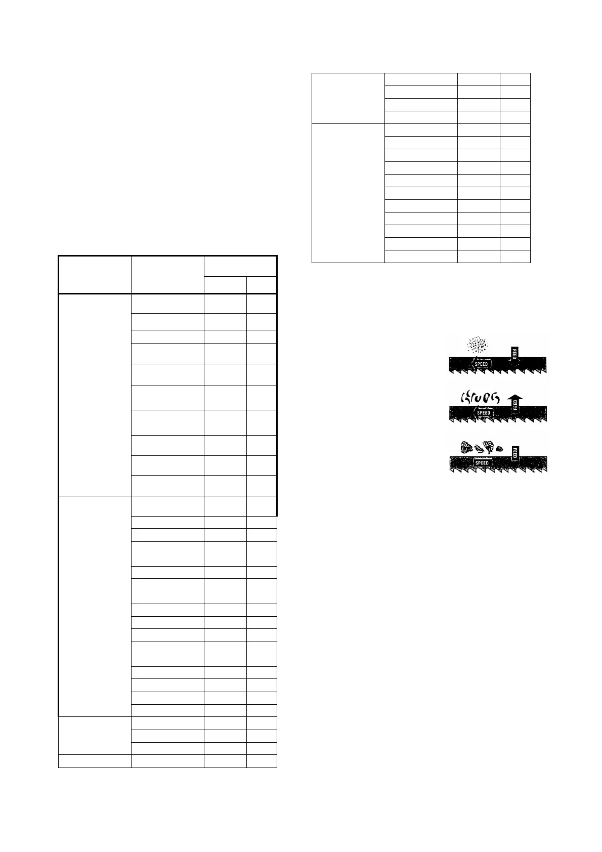
TELLTALE CHIPS
Chips are the best indicator of correct feed force. Monitor
chip information and adjust feed accordingly.
Thin or powdered chips – increase feed rate or reduce
band speed.
Burned heavy
chips – reduce feed rate
and/or band speed.
Curly silvery and warm chips –
optimum feed rate and band
speed.
9. ASSEMBLY
A 3/4 HP, motor, split phase or capacitor-start it
recommended for best economical performance.
Counterclockwise rotation is required. Note that rotation
can be reversed by ollowing directions
given on terminal or nameplate.
(1). Assemble the motor Mounting plate to the head using
the long bolt Note that the flat side of the plate faces up.
(2). Assemble the guard plate to the head using the
screw and Lock Washer and the Carriage Bolt Washer
and Wing Nut are used to secure the motor mounting
plate to the Guard plate through the slotted hole in the
Guard plate. These components also serve to position
and lock the motor in place for proper speed/ belt
adjustment.
(3). Place the spacer over the long Bolt and secure it wit
the nut .
(4). Secure the Motor to the Motor Mounting plate with
the four bolts and nuts. Note, that the motor shaft is
placed through the large opening in the Guard plate and
must be pareallel with the drive Shaft.
(5). Assemble the Motor Pulley, the smaller of the two
provided, to the motor shaft Note, the larger diameter
must be closest to the motor.
-6-