49
MULTIPLE INSTALLATIONS
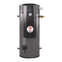
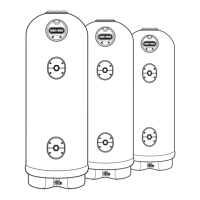
A multiple installation of Rheem 571D270 heat pump water heaters on a single manifold or multiple manifolds
is possible, using the Equa-Flow
®
manifold system, where large volumes of hot water are required. The Equa-
Flow principle will function with water heaters in line or in rows back to back or around an external corner. Due
to air flow requirements, it is not recommended to install the water heaters around an internal corner.
The cold water and hot water manifolds must be designed to balance the flow from each water heater. To
achieve this, there are basic installation requirements and principles which must be followed:
1. The maximum number of water heaters in a bank should be 8, however several banks of water heaters
can be installed.
2. The hot water line from the manifold must leave from the opposite end to which the cold water line enters
the manifold.
3. The water heaters must be of the same model.
4. The cold water line, cold and hot headers and hot water line must be sized to meet the requirements of
both AS/NZS 3500.4 and the application. Refer also to the table on page 50 for the minimum header and
branch pipe sizes.
5. A non-return valve, isolation valve and if required a pressure limiting valve and expansion control valve(s),
must be installed on the cold water line to the system.
6. A full flow gate valve or ball valve (not a stop tap, as used on a single water heater installation) must be
installed on both the cold water branch and hot water branch of each water heater.
7. An expansion control valve for each water heater can be installed into a brass Tee on the cold branch to
the tank after the gate valve or ball valve, in lieu of installing them on the cold water line to the system.
8. Non-return valves or pressure limiting valves must not be installed on the branch lines to the water heaters.
9. All fittings, valves and branch lines must be matched sets all the way along the manifold.
10. Sufficient space must be left to enable access, servicing or removal of
each water heater.
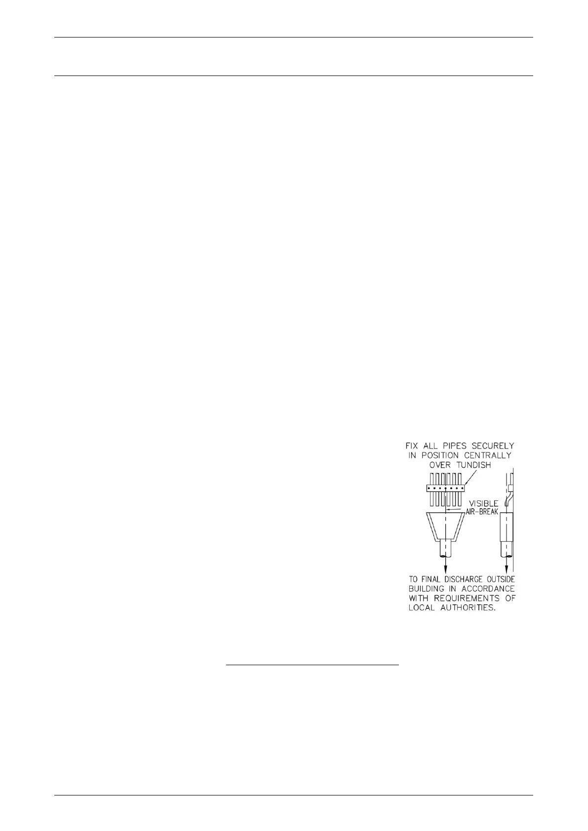
11. The temperature pressure relief valve drain line from each water
heater can terminate at a common tundish (funnel) with a visible air
break at each drain discharge point (refer to the diagram on page 49
and to “Relief Drain Line” on page 46).
Refer to the diagrams on pages 50 to 52 for installation, plant layout and
manifold details.
In addition to the basic installation requirements and principles of
manifolding, the following requirements for manifolding heat pump water
heaters of this model must be followed:
12. The heat pump water heaters can be installed in the same orientation
as a standard single water heater installation, with the cold and hot
water connections of the water heater parallel to the wall.
13. A minimum of 900 mm is required in front of each heat pump water heater to enable access, servicing or
removal of the water heater.
14. A circulated hot water flow and return system must not be returned back into the heat pump water heaters
(refer to “Circulated Flow and Return System” on page 41). If a circulated hot water system is required,
the flow and return line connects to either a secondary water heater to make up for the pipe heat loss in
the flow and return system or to an inline booster water heater(s), not the heat pump storage tank(s) (refer
to diagrams on page 51).