TM049 27L Continuous Flow Service Instructions
REV AL – Issued April 2019
This document is stored and maintained electronically by Rheem Technical Support. All printed copies are deemed “uncontrolled”.
BURNER GAS PRESSURE CHECK & ADJUSTMENT
Voltages up to 240 volts will be present within the water heater, take care
not to touch wiring terminals. Use an insulated tool when operating the
DIP switch or MIN and MAX buttons.
Minimum Burner Gas Pressure
1. Ensure all hot taps are closed.
2. Disconnect the remote temperature controller cables (if fitted)
from terminal block on underside of heater cabinet.
3. Remove the front cover from the water heater.
4. Locate the burner pressure test point on the burner manifold.
5. Remove the test point screw and fit manometer.
6. Open a hot tap slowly, to achieve the minimum flow rate at
which the burners will ignite.
7. Press and hold the MIN button (“1L” is shown on the LED
display) and observe the reading on the manometer.
8. Release the MIN button. If the reading observed in step 7 matches the minimum gas
pressure indicated on the rating label no further adjustment is required.
9. To adjust minimum gas pressure, press and hold the adjuster button (“LH” is shown on
the LED display). Note: The adjuster button must be held down through steps 9 to 12.
10. Press and hold the MIN button and observe the reading on the manometer.
11. Release the MIN button when the pressure indicated on the manometer matches the
minimum gas pressure listed on the rating label.
12. Release the adjuster button.
Maximum Burner Gas Pressure
13. Open the hot water tap fully to allow the water heater to ignite at
maximum operating flow. Multiple outlets may need to be opened
in order to achieve maximum water flow.
14. Press and hold the MAX button (“3H” is shown on the LED display)
and observe the reading on the manometer.
15. Release the MAX button. If the reading observed in step 14
matches the maximum gas pressure indicated on the rating label
no further adjustment is required.
16. To adjust maximum gas pressure, press and hold the adjuster
button (“LH” is shown on the LED display). Note: The adjuster
button must be held down through steps 16 to 19.
17. Press and hold the MAX button and observe the reading on the
manometer.
18. Release the MAX button when the pressure indicated on the manometer matches the
maximum gas pressure listed on the rating label.
19. Release the adjuster button and turn the hot tap/s off.
20. Remove manometer, refit the test point screw ensuring the seal is gas tight, reconnect
remote controllers if disconnected in step 2 and refit the front cover to the water heater.
Adjustment of the burner pressure will not overcome problems associated
with poor supply pressure or incorrect gas supply pipe sizing.
NOTE: If the burners extinguish or an error code appears during this procedure, release the
buttons, close the hot tap, clear the error code and recommence the procedure from step 5.
TEST
POINT
SCREW
WASHER
TEST POINT
ORIFICE
Test Point Gas Pressure Adjustment
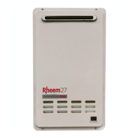
Continuous Flow Water Heater
86,87 Series, 022,024,027 Models
MANOMETER
MIN. BUTTON
MAX. BUTTON
ADJUSTER
BUTTON
DIP 1 SET OF
DIP SWITCHES
DIP SWITCH AND ADJUSTMENT BUTTONS
CONTINUOUS FLOW WATER HEATER
86,87 SERIES, 022,024,027 MODELS
1 2 3
4
OFF ON
DIP1
1 2
3
4
ON
1 2 3 4
OFF ON
DIP2
MIN MAX
ADJ
1 2 3 4
ON
 Loading...