2-STAGE COMMUNICATING INTEGRATED
FURNACE CONTROL (IFC)
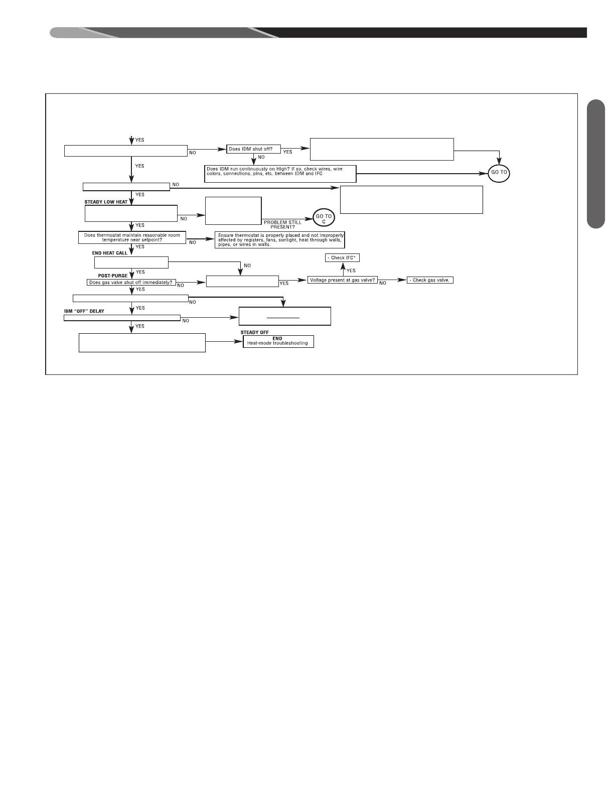
DIAGNOSTIC CHART
ECM = Constant CFM Blowers. (Electronically commutated motor)
TSTAT = Thermostat.
IDM = Induced Draft Motor (or Inducer).
I
FC = Integrated Furnace Control (or control board).
PS = Pressure Switch(es).
P
FC = Power Factor Correction Choke.
SE = Spark Electrode (s).
SSD = Seven Segment Display of Furnace control
C
OMM. = Communication.
I&O = Installation & Operation Instructions Manual.
1
) For communicating systems, Remove communications
connections from the T-stat (E1, E2) and use a jumper wire
between W1 & R also between R & W2 to set high stage gas
heat. For legacy systems ensure W2 & W1 are properly
connected and make sure both are energized w/ 240 AC after
the heat call is placed.
2) Set FAN switch to “AUTO” on T-stat.
3) Set thermostat to call for heat (set temp. differential to greater
than 10°F). (Comm. jumper W1 to R and W2 to R)
4) “H” should be displayed at “SSD’s” and should be on steady, if
flashing check dip switches (Item “1”).
IS
“
A capital H is displayed at IFC SSD’S” ?
Dual SSD’S “ON” ?
ST-A1194-52-01
Is thermostat heat call present?
For 24 VAC (Non-Comm. T-stat., is 24 VAC on W1 and/or W2 of
IFC. H or h should be displayed at SSD’S. ?
Is a fault code displayed at IFC?
(
After 10 Sec. a fault code will display anyway)
H or h only
For 1st 10 Sec. only
F
AULT
Under ”Troubleshooting”
i
n I & O Manual
C
heck W2 & connections,
replace or repair as
n
ecessary
Check t-stat, replace if
necessary.
(pre-purge) IDM runs for 30 sec. at low speed?
Does IDM Run for 60 Sec. and then off
for five minutes with fault
45, 46 or 57 displayed?
- See FAULT CODES under “Troubleshooting” in
I&O Manual.
ECM BLOWER “ON” DELAY
P2 - 6
P
2 - 4 on IFC.
NOTE: If IFC goes into lockout, shut off main power to unit, wait 30
seconds then reset power or removed heat call and re-establish.
- Check all connections between I.F.C. & E.C.M. Motor.
-
Check 24v to E.C.M. control (4pin connector, pin 1-4)
-
Check Dip switch setting.
-
Check P.F.C. choke. (if present)
-
Check all wiring and connections to P.F.C choke.
- Check fault code display, see “fault codes” in I & O. (if present)
- Check line voltage to motor (115VAC).
Does ECM blower start on high heat
speed 15-20 seconds after burners light?
Note: IFC SSD’s will display “22 or 33”.
?
Note: If good flame is not sensed a fault code
“11” or “13” will be displayed at SSD’s
Note: “12” is low flame sense, furnace should
still operate well.
Fault code
“45”, “46” or
“
57” displayed
at SSD’s.
CHECK:
- Fault codes at IFC SSD - see FAULT CODES under troubleshooting
in I&O manual.
- 24V Between IFC pins P2-5 & P2-4 of I.F.C.
- Make sure heat call present at T-stat.
- T-stat wires and connections
R
emove the 2nd stage heat call while low heat call
r
emains. Ensure 24 VAC to W1 & 0 VAC to W2
Check to make sure test mode dip switches are properly set.
-
Check all connections between IFC and ECM motor.
-
Check 24V to ECM Motor. (low voltage connector, pins 1 & 4)
-
Check P.F.C. Choke.
-
Check all wiring and connections to P.F.C. choke.
- Check fault code display and see “fault codes” In I & O.
Does I. B. M. energize at low speed?
A
fter Blower on delay, Does IDM switch to low speed
and remain at low speed after switching?
Does furnace continue to operate at low
fire until T-stat satisfied or heat call
removed?
E
nsure T-stat not
switching to high fire or
test mode not timing out
(1 hour limit)
Fault code displayed?
See FAULT CODES under
t
roubelshooting in the I & O Manual
Does IDM Shut off after post purge?
Does I. B. M. shut off after 90 seconds? (plus slew)
D
ouble check - is heat call
completely off at IFC?
** System will attempt to light 4 times. Voltage Is present at gas valve for
only 7 seconds during each ignition trial. System will enter a 1 hour
l
ockout after 4 attempts.
Be sure to note dip switch settings before troubleshooting.
L
ower case “h”
Capital “H”
-
Check line voltage at I.D.M.
-Check Wires And connections between I.D.M. and I.F.C.
-Ensure line voltage between P3, Pin 2 & P3, Pin 3 of I.F.C. (High IND Output).
-
Check I.D.M. Capacitor.
S
park Electrodes (SE) Energize?
See I&O.
Does gas valve remain
energized?
PROBLEM
P
ERSISTS ?
CHECK:
AIRFLOW - ensure no restrictions, such as dirty filter, blower wheel,
dampers or closed registers, Etc. exist.
L
IMITS - ensure good wire and connections between I.F.C. and all limits.
m
akes sure limits are not open when circulating air temperature is within a
specific range.
ROLLOUTS - Ensure rollouts or overtemperature limits do not need to be
reset. make sure no flame rollout in burner compartment due to blocked flue
o
r heat exchanger or combustion restriction.
OVERFIRE - ensure furnace is not overfired (temp rise is above stated
r
ange). Check gas valve, proper orifice size, gas presure
C
HECK:
-Grounding on I.F.C. in place and continuity between screw and field
-installed ground.
-Flame sense rod clean (clean if nessessary).
-
Wire continunity between flame sense rod and Pin P2-7 on I.F.C.
-Flame carries across all burners, and all burners stay lit.
R
emove heat call by setting
T
-stat below room temp.
Remove power to furnace, open blower compartment
a
nd restore dip switches to original settings. Replace
blower door. Restore power to unit.
- Check wire and all connections between I.F.C.and I.D.M
- Check for 115 VAC on P3-1 & P3-3.
- Check I.D.M. capacitor.
- Check I.D.M. low speed. Replace if neccessary.
C
G
0 T0
I
Does the IDM Start on Low Speed?
PROBLEM PERSISTS
REPEAT THIS SEQUENCE UNTIL TROUBLE- FREE OPERATION
DISCONNECT POWER BEFORE SERVICING.
SERVICE MUST BE BY A TRAINED,
QUALIFIED SERVICE TECHNICIAN.
scotchbrite pad)
.
S
T-A1194-52-01
 Loading...