28
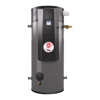
Outlet Side
Outlet (Manifold) Pressure
Tap Boss
Inlet Pressure Tap Boss
Inlet Side
Flush The Tank
Elements in the water such as lime and iron may
accumulate in the heater. Accumulation of these
elements can keep your water heater from oper-
ating
at peak efficiency and may lead to premature
tank failure. It is recommended that the tank is
drained and flushed thoroughly twice a year to
prevent buildup
Maintenance
Check The Combustion System
On an annual basis, verify that the combustion
system is operating within acceptable param-
eters. Gas pressures and combustion measure-
ments can be used to verify proper operation.
Check the inlet gas pressure to the gas control.
The pressure should be greater than 6"W.C. (nat-
ural gas) and 8" W.C. (LP gas) when the burner
is operating at high fire. Gas pressure shall not
exceed 14" W.C. when the burner is off
Measure the products of combustion in the
exhaust vent. At maximum input, the % O2 in the
exhaust gas should be in the range of 3.0 - 4.5%.
CO should be less than 25 ppm.
In the combustion readings are outside of the
specified ranges, check the manifold pressure
on the gas control at the outlet pressure tap. See
figure 21 for the location of this pressure tap on
the gas control. At maximum input and minimum
vent lengths with 4" pipe, the manifold pressures
for each model are given in Table 6.
Contact Rheem if the measured manifold pressure varies by +/-0.5" W.C. or greater from the specified
value.
Table 5
Manifold Pressures
APPROVED Manifold
ALTITUDE Pressure
TYPE RANGE (.) ( in. W.C.)
GHE119-500 NAT. 0 - 2000 -2.4
GHE125-500A NAT. 0 - 2000 -2.4
GHE119-500HA NAT. 2000 - 7800 -2.1
GHE125-500A HA NAT. 2000 - 7800 -2.1
THE119-500 NAT. 0 - 2000 -2.4
THE125-500A NAT. 0 - 2000 -2.4
THE119-500 HA NAT. 2000 - 7800 -2.1
THE125-500A HA NAT. 2000 - 7800 -2.1
GHE119-500 LP 0 - 2000 -2.0
GHE125-500A LP 0 - 2000 -2.0
GHE119-500HA1 LP 2000 - 5400 -1.3
GHE119-500HA2 LP 5400 - 7800 -
1.
3
GHE125-500A HA1 LP 2000 - 5400 -1.3
GHE125-500A HA2 LP 5400 - 7800 -1.3
THE119-500 LP 0 - 2000 -2.0
THE125-500A LP 0 - 2000 -2.0
THE119-500HA1 LP 2000 - 5400 -1.3
THE119-500HA2 LP 5400 - 7800 -1.3
THE125-500A HA1 LP 2000 - 5400 -1.3
THE125-500A HA2 LP 5400 - 7800 -1.3
Table 6 - Manifold Pressures.
Figure 22

 Loading...