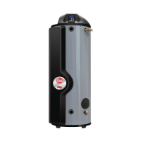
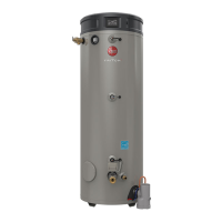
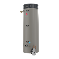
WATER CONNECTIONS — This water heater may be connected indi-
vidually, in multiples with others, or with an external hot water storage
tank.
Inlet water connections are made to the lower coupling on the heater,
and outlet water connections are made to the upper coupling.
Each water heater is supplied with the necessary components (Dif-
fuser tubes) to make the water connections that will ensure proper
performance. The components are supplied in a bag attached to the
water heater. If special instructions are required for any specific water
heater, they will be included in the bag.
Cap or plug unused connections. Use only clean, new galvanized steel,
copper or approved plastic pipe for water connections. Local codes
or regulations shall govern the exact type of material to be used. The
installation of unions on the inlet and outlet water lines and a shut-off
valve in at least the cold water inlet line is recommended, so the water
heater may be easily disconnected for servicing. Dielectric unions are
not required for protection of water heater.
When this water heater is supplying general purpose hot water require-
ments for use by individuals, a thermostatically controlled mixing valve
is recommended to reduce the risk of scald injury. Contact a licensed
plumber or the local plumbing authority for further information.
Thermometer(s) should be installed so that they indicate the tempera-
ture of the water at or near the outlet of the water heater and storage
tank(s) if provided. See Fig. 2.
3. RELIEF VALVE — A new factory installed combination pressure and
temperature relief valve, complying with the Standard for Relief Valves
and Automatic Gas Shutoff Devices for Hot Water Supply Systems,
ANSI Z21.22, or Standard CSA 4.4, Temperature, Pressure, Tempera-
ture and Pressure Relief Valves and Vacuum Relief Valves is provided
with the water heater. No valve is to be placed between the relief valve
and the water heater. For a circulating tank installation, the separate
storage tank(s) must have similar protection. The pressure rating of
the relief valve must not exceed 150 psi (1034 kPa) (160 psi for ASME
models), the maximum working pressure as marked on front of the
water heater.
Connect the outlet of the relief valve to a suitable open drain.
The discharge line must pitch downward from the valve to allow
complete draining (by gravity) of the relief valve and discharge
line, and be no smaller than the outlet of the valve. The end of the
discharge line should not be threaded or concealed and should be
protected from freezing. No valve of any type, restriction or reduc-
er coupling should be installed in the discharge line. Local codes
shall govern the installation of relief valves.
The Btu/h rating of the relief valve must equal or exceed the Btu/h input
of the water heater as marked on its rating plate.
4. GAS SUPPLY — The inlet gas pressure to the water heater must not
exceed 10.5” w.c. (2.6 kPa) for Natural gas and 13.0" w.c. (3.2 kPa) for L.P.
gas. The minimum inlet gas pressure (with main burner on) is shown on
the rating plate. Check to see if high or low gas pressure is present and
then contact the gas company for correction.
The gas line should be of adequate size to prevent undue pressure
drop. Sizing based upon information in Table 2. No additional allowance
is necessary for an ordinary number of fittings.
A ground joint union and manual shutoff valve should be installed in
the gas line near the water heater so that the burner assembly may
be easily removed. The shut-off valve must be readily accessible for
turning on or off. See Fig. 2.
Where a sediment trap is not incorporated as part of the appliance, a
sediment trap shall be installed downstream of the equipment shutoff
valve as close to the inlet of the appliance as practical at the time of
the appliance installation. The sediment trap shall be either a tee fitting
with a capped nipple in the bottom outlet or other device recognized
as an effective sediment trap. See Fig. 2.
LEAK TESTING — The water heater and its gas connections MUST
be leak tested at normal operating pressure before it is placed in op-
eration. Turn ON the manual gas shut-off valve near the water heater.
Use a soapy water solution to test for gas leaks at all connections and
fittings. Bubbles indicate a gas leak that must be corrected. The water
heater factory connections to the gas valve should also be leak tested
after placing the water heater in operation.
NEVER use open flame to test for gas leaks, as bodily injury or prop-
erty damage could result.
PRESSURE TESTING THE GAS SUPPLY SYSTEM — The water
heater and its manual gas shut-off valve MUST be disconnect-
ed from the gas supply piping system during any high pressure
testing of that system at pressures in excess of 1/2 psi
(14” w.c. / 3.5 kPa).
The water heater MUST be isolated from the gas piping system
by closing the manual gas shut-off valve during any pressure test-
ing of the gas supply piping at pressures equal to or less than
1/2 psi (14” w.c. / 3.5 kPa).
5.
CONDENSATE
Filling The Condensate Trap:
THE CONDENSATE TRAP MUST BE FILLED WITH WATER, BEFORE
OPERATING WATER HEATER.
To fill the trap (Refer to Figure 1), remove the plastic cap on the left
side of the trap. Pour about one (1) cup of water into the trap and then
re-install the plastic cap.
This is a condensing high efficiency appliance, therefore this unit has
a condensate removal system. Condensate is nothing more than water
vapor, derived from the combustion products. This condensate does
have a low pH and condensate removal must comply with all local
codes. See information below for optional Condensate Neutralizer, if
required. It is very important that the condensate line is sloped away
from and down to a suitable inside drain. If the condensate outlet on
this unit is lower than the drain, you must use a condensate removal
pump. It is also very important that the condensate line is not exposed
to freezing temperatures, or any other type of blockage. Plastic tubing
should be the only material used for the condensate line. Steel, brass,
copper, or other metals will be subject to corrosion and deterioration.
A second vent may be necessary to prevent condensate line vacuum
lock if a long horizontal run is used. Also an increase to 1" tubing may
be necessary.
6
Installation
WARNING
!
 Loading...