48
Pin 2 to stepper modulating gas valve
connector Pin 2 (RX)
Pin 3 to stepper modulating gas valve
connector Pin 3 (TX)
Pin 4 to stepper modulating gas valve
connector Pin 4 (COMMON)
Pin 5 to stepper modulating gas valve
connector Pin 5 (MVTH)
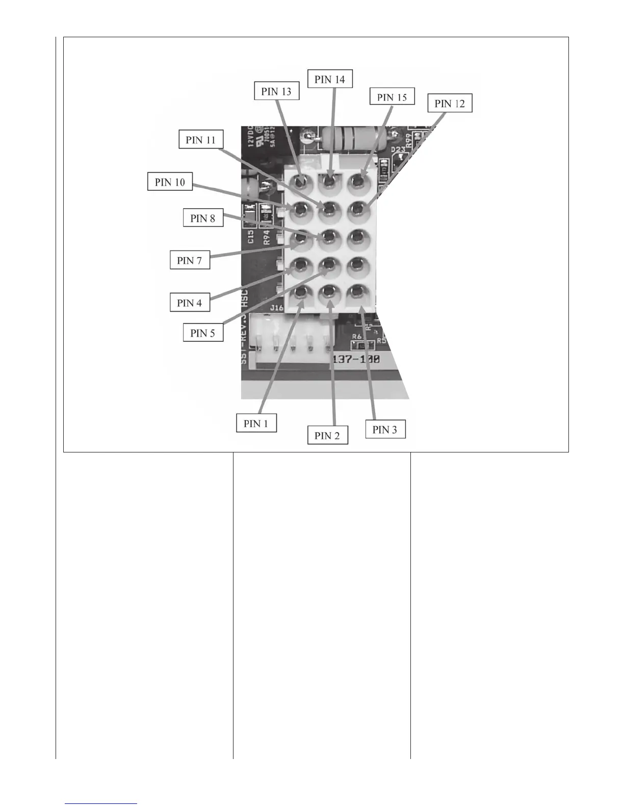
15-PIN MATE-N-LOK CON-
NECTOR (J1) (see Fig 39)
The 15-pin Mate-n-Lok style connector
provides connections for a variety of
inputs and outputs to the furnace con-
trol. The fl
ame sense, pressure switches
sense and limits sense (Main Limit,
MRLC and HALC) are connected to the
I.F.C. through this connector. Reference
the wiring diagram for the furnace print-
ed in this document or on the inside of
the furnace blower door for pin assign-
ments for troubleshooting.
For troubleshooting purposes, follow the
wiring diagram and troubleshooting flow-
chart supplied in this manual and
on t
he
inside of the furnace blower door.
Additionally, the pin designations for
the connector are specified below:
Pin 1. HLI HIGH LIMIT INPUT
Pin 2. PS1 LOW PRESSURE SWITCH OUT-
PUT
Pin 3. RLI ROLL OUT SWITCH INPUT
Pin 4. TH 24V HOT
Pin 5. GND GROUND
Pin 6. NOT USED
Pin 7. PSO PRESSURE SWITCH OUTPUT
Pin 8. MVC MAIN VALVE COMMON
Pin 9. ILI INDUCER LIMIT INPUT
Pin 10. HLO HIGH LIMIT OUTPUT
Pin 11. TR 24V RETURN
Pin 12. PS2 SEC
OND P
RESSURE SWITCH
OUTPUT
Pin 13. MVL MAIN VALVE LOW
Pin 14. MVH MAIN VALVE HIGH
Pin 15. AXI AUXILIARY SWITCH INPUT
COMMUNICATING ECM
MOTOR COMMUNICATIONS
(CONTROL) CONNECTION
(E114)
This connector sends and receives
messages to and from the blower
motor through a single peer-to-peer
network. The blower motor does not
communicate on the same commu-
nications buss as the furnace, con-
denser and thermostat. Further, a
d
ifferent communications protocol is
used.
For troubleshooting purposes, follow
the wiring diagram and troubleshoot-
ing flowchart supplied in this manual
and on the inside of the furnace
blower door. Additionally, the pin
designations for the connector are
specified below:
Pin 1 to communicating blower
motor connector Pin 1 (+V)
Pin 2 to communicating blower
motor connector Pin 2 (TX)
Pin 3 to communicating b
lower
m
otor connector Pin 3 (RX)
Pin 4 to communicating blower
motor connector Pin 4 (C)
FIGURE 39
15-PIN CONNECTOR; J1 WITH PIN DESIGNATIONS