55
See the section of this document titled
THERMOSTATS (under the sub-sec-
tion titled NON-COMMUNICATING
THERMOSTATS) for information on
how to wire the thermostats for each of
the configurations below.
In non-communicating systems, the
heating cycle is always initiated by a 24
volt signal on W1. When the controller
senses 24 volts on W1, the following
sequence occurs:
MODULATING FUNCTION:
(Modulating function with a
non-com-
municating thermostat only applies
when both switches S4-2 and S4-3 are
in the “OFF” position and a non-com-
municating modulating thermostat
(specified for use with the furnace) is
installed as shown in Figures 53-55.)
After the warm-up period, the furnace
will respond to the thermostat demand
by adjusting the gas valve pressure
and blower speed between 40% and
100% of maximum heating capacity.
TWO-STAGE FUNCTION:
(Two-stage function only applies when
both switches SW2-2 and SW2-3 are
in the “ON” position and a two-stage
thermostat is installed as shown in
Figure 57.)
FURNACE OPERATION
USING NON-COMMUNICAT-
ING MODULATING, SINGLE-
STAGE, AND TWO-STAGE
THERMOSTATS (CONSULT
THE SECTION OF THIS
DOCUMENT TITLED NON-
COMMUNICATING THER-
MOSTATS FOR WIRING DIA-
GRAMS)
The modulating furnace is capable of
operating with a single-stage or a two-
stage thermostat as well as the modu-
lating thermostat or fully communicating
thermostat specified for use with the fur-
nace. Fully communicating thermostat
functions and operations are explained
in detail in the sections of this manual
titled COMMUNICATING SYSTEMS
and THERMOSTATS (under the sub-
section titl
ed C
OMMUNICATING THER-
MOSTATS).
Based on the dipswitch settings of S4-2
and S4-3, the furnace will operate with
either single-stage or two-stage ther-
mostats as a modulating system using
an algorithm that utilizes three distinct
firing rates; 40%, 65% and 100% of the
furnace heating capacity (See below for
opera tion of each). See Figure 41 to
determine which dipswitch settings are
necessary for operation
w
ith a modulat-
ing, single-stage or two-stage thermo-
stat.
After the blower on-delay period, the
furnace will respond to the thermo-
stat demand by adjusting the gas
valve pressure and blower heating
speeds to the “W” signal values.
“W1” only = 40% gas valve pres sure
and blower heating speed. “W2” =
65% gas valve pressure and blower
heating speed for the first five min-
utes and 100% thereafter. Also, if
the c
all for heat ends, the furnace
terminates at the present rate.
SINGLE-STAGE FUNCTION (“W”
signal only) :
(Single-stage function only applies
when both switches S4-2 and S4-3
are in the “OFF” position and a
single-stage thermostat is installed
as shown in Figure 56.)
After the blower on-delay period, the
furnace will respond to the thermo-
stat demand by altering the gas
valve pressure and blower speed as
follows:
Phase 1: 0 to 5 minutes = 40% of
furnace capacity (gas valve output
and blower speed)
Phase 2: 5 to 12 minutes = 65% of
fur nace capacity (gas valve output
and blower speed)
Phase 3: After 12 min
utes = 1
00%
of fur nace capacity (gas valve out-
put and blower speed)
NOTE: If the call for heat ends dur-
ing any phase, the furnace will ter-
minate imme diately at the firing rate
of that phase.
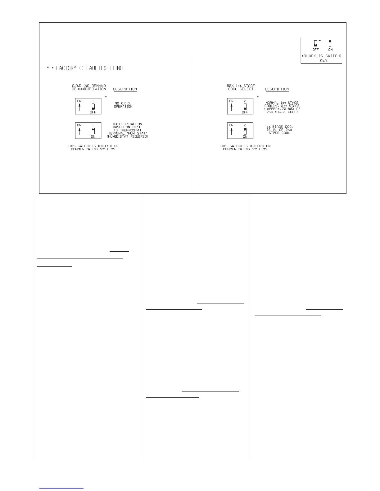
FIGURE 42
DIPSWITCH BANK S5 COOLING / O.D.D. SELECT
ST-A1171-01