54
A. The thermostat is satisfied and the
call for heat is removed.
B. The furnace has been in test mode
continuously for sixty minutes, at
which time the furnace control (IFC)
will exit the test mode and proceed
to normal heating operation as con-
figured. Test mode can not be acti-
vated again unless line voltage
power to the furnace is cycled off
and back on. This is true even if the
dipswitches remain config
ur
ed to the
test settings.
To set the furnace for normal
oper ation:
1. Set the thermostat mode to OFF.
Always allow furnace to complete
the cool down cycle.
2. Switch the 115 volt power to the
furnace OFF. Do not change
set tings with control energized.
3. Remove furnace blower door.
4. Position dipswitches S4-2 and
S4-3 for modulating/single-stage
mode or 2-stage mode.
5. Replace furnace blower door.
6. Switch the
11
5 volt power to the
furnace ON.
7. Set the thermostat as desired.
Switch (SW2-1) Call Voltage at “HUM” Action
ON COOL 24 Normal Cool (c or C)
ON COOL 0 Dehum Cool (cd or Cd)
ON Heat 24 Hum Contacts Closed.
ON Heat 0 Hum Contacts Open.
OFF COOL 24 Normal Cool (c or C)
OFF COOL 0 Normal Cool (c or C)
OFF Heat 24 Hum Contacts Closed.
OFF Heat 0 Hum Contacts Open.
1. Normal ignition sequence
2. A calibration cycle will be performed
unless the Test Switches are set for
Test 40%. The LED status indicator
will flash “H” or “h” during the cali -
brat
ion c
ycle.
NOTE: The supply air sensor (field
installed) is required for the furnace cali-
bration cycle. If the air sensor is faulty,
or not properly connected, the fur nace
will not attempt a calibration cycle and
will operate on factory default parame-
ters pre-pro grammed into the micro-
processor.
After calibration, the furnace will then
adjust to the desired Test capacity. This
allows time for the technician t
o check
steady-state operation and evaluate fur-
nace performance.
The furnace will operate at the fixed
Test capacity until one of the following
conditions:
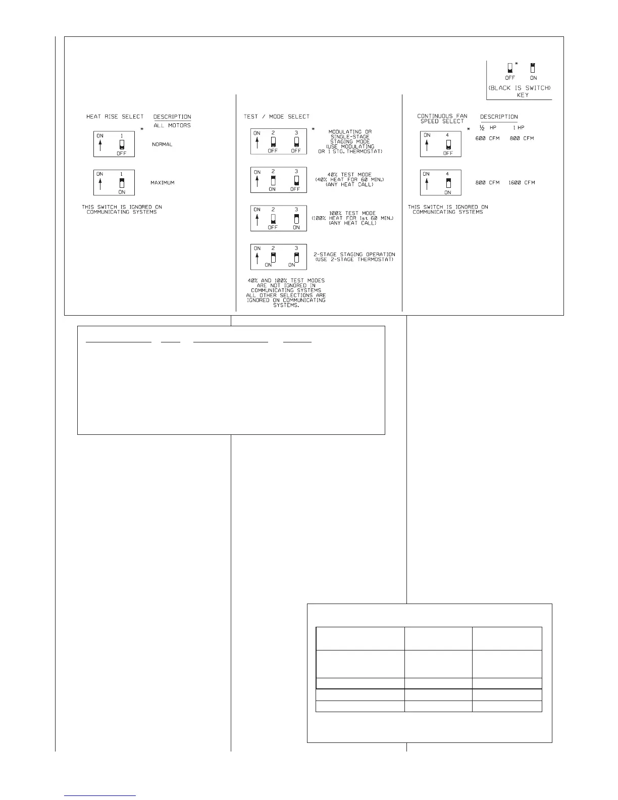
FIGURE 41
DIPSWITCH BANK S4 TEST MODE SELECT
TABLE 18
SW2-2 AND SW2-3 MODE SELECTION SETTING
Note: The “Test 40%” and “Test 100%” settings will time out
and become invalid one hour after power reset.
Mode
Switch S4-2
Position
Switch S4-3
Position
Modulating / Single-
Stage
Test 40%
Test 100%
Two Stage
OFF
ON
OFF
ON
OFF
OFF
ON
ON
ST-A1164-01