58
COMMUNICATING SYS-
TEMS
The modulating furnace is capable
of communicating with a thermostat
and condenser to improve cooling
and heat-pump airflow, displaying
active faults and active furnace
information at the thermostat and
improved diagnostics and trou-
bleshooting.
WIRING A FURNACE FOR COM-
MUNICATIONS.
Maximum wire lengths and notes
about wiring communicating sys-
tems are noted below.
MAXIMUM COMMUNICATING
W
IRE LENGTHS (1, 2, R & C)
Max Wire Length – Thermostat to
Furnace = 100 FT @ 18 AWG*
Max Wire Length – Furnace to
Condenser = 125 FT @ 18 AWG*
Notes:
1. When using twisted pairs, be
sure the wires connected to pins
labeled “1” (recommended wire
color = green) and “2” (recom-
mended wire color = yellow) are
a twisted pair.
2. Wires may be solid or stranded..
3. *Wire gage smaller than 18 AWG
is not approved or recomm
ended
f
or this application.
4. When using existing wire from a
previous installation, be sure to
trim the tip of the wire back past
the insulation and strip a small
amount of insulation from the
wire to expose clean new copper
for the communicating connec-
tions. Fresh copper must be
exposed when making the com-
municating connections or com-
munications may not be properly
established.
Figure 45 is the wiring diagram f
or
connecting the furnace to an
approved ClimateTalk communicat-
ing thermostat and approved Rheem
or Ruud communicating condenser.
The only approved configuration is
to install dedicated wires directly
from the furnace to the thermostat
and a separate set of dedicated
wires directly from the furnace to the
condenser. Note: The only
approved configuration requires that
four dedicated wires (1, 2, R a
nd C
)
be installed from the furnace to the
condenser.
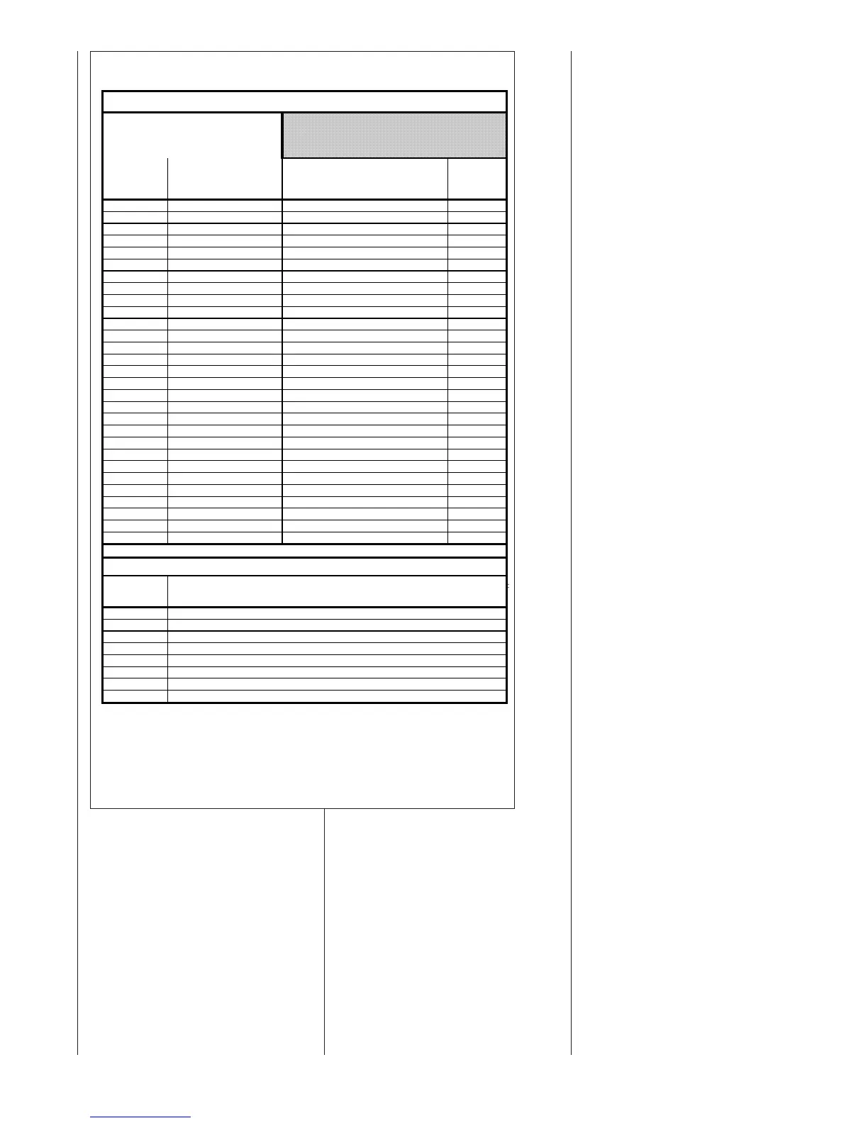
TABLE 19
LIST OF FAULT CODES AND NORMAL OPERATION CODES
FAULT CODE # TEXT MESSAGE MESSAGE TO HOMEOWNER
NUMBER
(displayed at
furnace)
d1 NO SHARED DATA "Call For Service" & "CHECK FURNACE" d1
d4 MEM CARD INVALD (None) d4
d5 CARD-HRD CNFLCT (None) d5
d6 BLWR HP CNFLCT "Call For Service" & "CHECK FURNACE" d6
d7 BLWR MFG CNFLCT "Call For Service" & "CHECK FURNACE" d7
d8 OLD SHARED DATA (None) d8
d8 OLD SHARED DATA "Call For Service" & "CHECK FURNACE" d8
h
GAS HT ON-NO V
(None) h (steady)
10
IGN 1 HR RTRY "Call For Service" & "CHECK FURNACE"
10
11 FAILED IGNITION (None) 11
12 LO FLAME SENSE (None) 12
13 FLAME LOST (None) 13
14 UNEXPCTED FLAME "Call For Service" & "CHECK FURNACE" 14
22 MAIN LIMIT OPEN (None) 22
23 HALC LIMIT OPEN "Call For Service" & "CHECK FURNACE" 23
26 LINE_NTRL RVRSD "Call For Service" & "CHECK FURNACE" 26
33 MRLC OPEN "Call For Service" & "CHECK FURNACE" 33
44 LPC CLOSED "Call For Service" & "CHECK FURNACE" 44
45 LPC OPEN "Call For Service" & "CHECK FURNACE" 45
46 LPC OPEN "Call For Service" & "CHECK FURNACE" 46
55 HPC CLOSED "Call For Service" & "CHECK FURNACE" 55
57 HPC OPEN "Call For Service" & "CHECK FURNACE" 57
60 BLWR FLT-RUN (None) 60
61 BLWR FLT-NO RUN "Call For Service" & "CHECK FURNACE" 61
66 BLOWER OVRSPEED (None) 66
68 NO BLWR COMM "Call For Service" & "CHECK FURNACE" 68
71 NO INDUCER COMM "Call For Service" & "CHECK FURNACE" 71
77 NO GV FEEDBACK "Call For Service" & "CHECK FURNACE" 77
93
CONTROL FLT "Call For Service" & "CHECK FURNACE" 93
DISPLAYED AT
FURNACE
0
c
C
F
hp
HP
H (steady)
h (steady)
Low-stage heat-pump operation
Furnace heat with valid modulation signal or Communicating heat signal
Standby mode - no thermostat calls, no active faults.
Low-stage cooling (not displayed in communicating modes)
High-stage cooling (displayed during both low and high cooling in communicating mode)
NOTE: To clear current fault codes in the furnace control buffer, push and hold down the "FAULT RECALL"
button (SW1) for three seconds. The right-most Seven-Segment Display will energize the upper and lower
horizontal members (turned vertical in the application) for four seconds as confirmation that the faults have
been cleared. This will clear faults in the buffer displayed at power-up on the seven-segment display and in
the user menu displayed at the thermostat.
NOTE: The following fault codes will not be stored back-to-back in the fault buffer. These will only be stored
in the buffer if the previous fault stored was a different fault. 11, 45, 46 and 57.
FAULT CODES / MESSAGES
Continuous Fan Operation
NORMAL OPERATION CODES / MESSAGE
DESCRIPTION (Neither a code or message is displayed at the thermostat. A code
number only is displayed at the furnace control.)
MESSAGE TO TECHNICIAN at TSTAT (note:
Fault Code Number and Fault Code Text are
displayed in two separate regions of T-Stat
display)
High-stage heat-pump operation
Heat call with no valid modulation signal (legacy modes only)