45
SEVEN SEGMENT
DISPLAY:
The furnace control displays status and
diagnostic information at the Seven
Segment Display. When viewing the
display the observer should be aware
that the top of the digit is to the left and
the bottom of the digit is to the right
(upflow models). Figure 37 details
proper reading of the diagnostic dis-
play. Operation is described in detail
below:
STANDBY MODE:
“0” displayed steady.
HEATING M
ODE:
“H” is displayed followed by a one digit
number. The number represents the
current firing rate. For example “H7”
would represent heating mode operat-
ing at 70% of firing rate (“H0” repre-
sents 100% heat). This is then toggled
with two numbers which indicate the
CFM of the main circulating blower
divided by 100. For example, if “18” is
displayed, the furnace is attempting to
deliver 1800 CFM o
f a
ir.
For example, if “H7” is displayed fol-
lowed by “14” (toggling), this would
indicate that the furnace is operating at
70% heat with the airflow operating at
1400 CFM.
COOLING MODE:
“C” is displayed. This is then toggled
with two numbers which indicate the
CFM of the main circulating blower
divided by 100. For example, if “18” is
displayed, the furnace is attempting to
deliver 1800 CFM of air.
For exampl
e, if “C” is displayed fol-
lowed by “12” (toggling), this would
indicate that the system is in air con-
ditioning mode with the airflow oper-
ating at 1200 CFM.
HEAT PUMP HEAT MODE
(COMMUNICATING DUAL-FUEL
SYSTEMS):
“HP” is displayed. This is then tog-
gled with two numbers which indi-
cate the CFM of the main circulating
blower divided by 100. For example,
if “18” is displayed, the furnace is
attempting to deliver 1800 CFM of
air.
For example, if “HP” is displayed fol-
lowed by “12” (toggling), this would
indicate that the system is in heat-
pump heat mode with the airflow
operating at 1200 CFM.
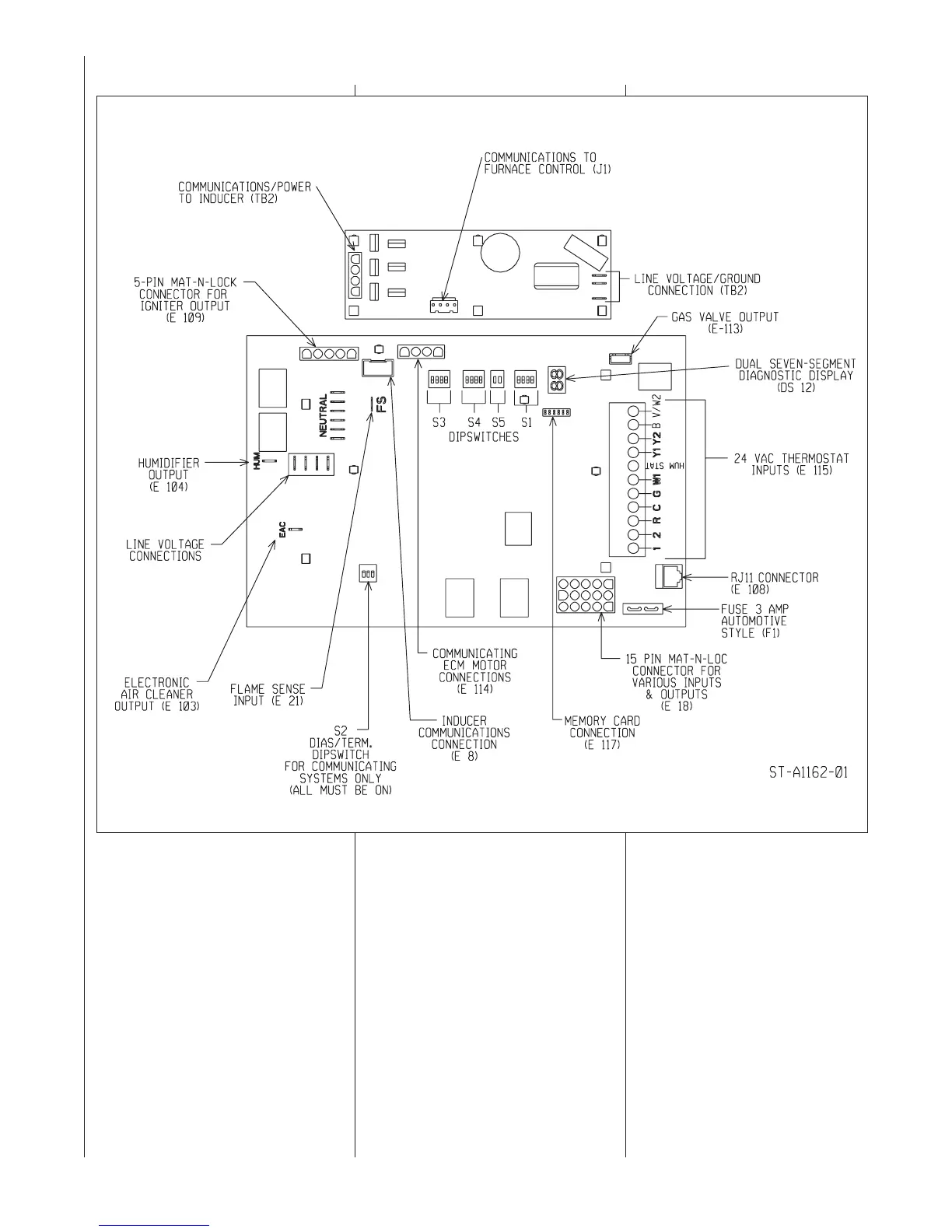
INTEGRATED FURNACE CONTROL (I.F.C.)
FIGURE 36
MODULATING CLIMATE-TALK COMMUNICATING FURNACE CONTROL (RHEEM # 62-102783-01)