14
4.3 CONTROL WIRING
IMPORTANT: Class 2 low voltage control wire should not be run in conduit with power
wiring and must be separated from power wiring, unless Class 1 wire of proper voltage
rating is used.
• Low voltage control wiring should be 18 AWG color-coded (105°C minimum). For
lengths longer than 100 ft., 16 AWG wire should be used.
• Low voltage control connections are made by extending wires from top of air handler
using wire nuts.
• See wiring diagrams attached to indoor and outdoor sections to be connected
• Do not leave excess field control wiring inside unit, pull excess control wire to outside
of unit and provide strain relief for field control wiring on inside of cabinet at point
wiring penetrates cabinet.
• Make sure, after installation, separation of control wiring and power wiring has been
maintained.
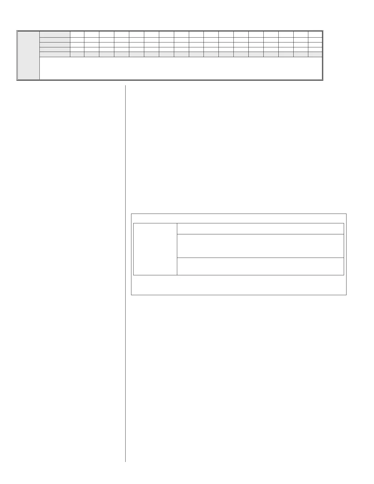
FIELD WIRE SIZE FOR 24 VOLT THERMOSTAT CIRCUITS
Thermostat Load - Amps
3.0
2.5
2.0
16
16
18
50
14
14
16
100
12
12
14
150
10
12
12
200
10
10
12
250
10
10
10
300
SOLID COPPER WIRE - AWG.
Length of Run - Feet (1)
(1) Wire length equals twice the run distance.
NOTE: Do not use control wiring smaller than No. 18 AWG between thermostat and outdoor unit.
S
U
P
P
L
Y
W
I
R
E
L
E
N
G
T
H
F
E
E
T
S
UPPLY CIRCUIT AMPACITY
NOTE: WIRE BASED ON COPPER CONDUCTORS 75°C MINIMUM RATING.
FOR MORE THAN 3 CONDUCTORS IN A RACEWAY OR CABLE, SEE
N.E.C. FOR DERATING THE AMPACITY OF EACH CONDUCTOR.
12
12
14
14
15
10
10
12
12
20
8
10
10
10
25
8
10
10
10
30
8
8
8
8
35
6
8
8
8
40
6
6
8
8
45
6
6
6
6
50
4
6
6
6
60
4
4
4
4
70
3
4
4
4
80
3
3
3
3
90
2
3
3
3
100
2
2
2
2
110
1
1
1
1
125
0
0
0
0
150
00
00
00
00
175
4.2 COPPER WIRE SIZE - AWG. (3% VOLTAGE DROP)
200 [61]
150 [46]
100 [30]
50 [15]
 Loading...