Do you have a question about the RHINO 832 and is the answer not in the manual?
Diagram illustrating the Rhino 832 control panel and connected devices.
Introduces the Rhino 832 as a wired/wireless alarm panel with GSM modem and mobile app integration.
Details the system's capabilities regarding zones, partitions, users, and system options.
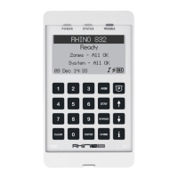
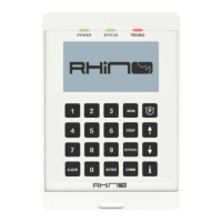
Describes the functionality and connection of up to 4 Graphic LCD remote keypads.
Lists available wireless devices compatible with the Rhino 832 system.
Explains the Rhino UDL software for programming and diagnostics.
Planning the placement of detection devices, keypads, and modules.
Instructions for securely mounting the control panel in a suitable location.
Guidance on mounting and connecting remote keypads to the control panel.
Visual representation of the Rhino 832 control panel's main components and connections.
Details the primary PCB and its connection points for various modules.
Describes the function of key terminals on the PCB, including bus, zone, output, and power connections.
Explains how to connect devices to the network bus and expanders.
Instructions for securely mounting the control panel on a wall.
Guidance on connecting 8-zone and 16-zone wired expanders.
Describes connecting remote keypads, cable types, and overcoming voltage drop.
Instructions for connecting a power supply for the system.
Details different methods for wiring wired detection devices to zones.
Configuration for detectors with a normally closed alarm output.
Configuration for detectors with a normally open alarm output.
Configuration using EOL resistors for normally closed contacts.
Configuration using EOL resistors for normally closed contacts with tamper.
Details the RH-100 wireless door contact sensor and its features.
Describes the RH-101 interface for third-party PIR devices.
Details the RH-200 wireless indoor PIR detector.
Describes the Raptor gate module for wireless input/output control.
Explains the features and buttons of the Raptor wireless remote control.
Wiring instructions for connecting external sounders and strobes.
Wiring examples for using panel outputs to drive auxiliary devices like LEDs.
Critical warnings and safety guidelines before applying power to the system.
Steps to access the engineer's programming menu using a code.
How to move through the configuration menus using keypad keys.
Lists and describes various zone types: Not Used, Final Exit, Follower, Intruder, Perimeter.
Details zone types like Fire, PA Silent, PA Audible, Medical, 24 Hour, Tamper.
Describes the 'Normally Closed' wiring configuration for detectors.
Configuration for detectors with a normally open alarm output.
Explains Single EOL - NC and Double EOL wiring configurations.
Steps for programming wireless zones, including type, serial, and learn methods.
How to manually enter the serial number for a wireless device.
Process for automatically learning wireless device serial numbers via tamper activation.
Configurable options like Double Knock, Crossover, and Momentary Keyswitch for zones.
How to assign zones to one of the four available system areas.
Settings for manually or automatically bypassing zones during arming.
Configuration for audible chime tones when zones are activated.
Configuration of exit delay, entry delay, and bell duration timers for areas.
Settings for 'Final Exit' and 'Timed Exit' arming modes for areas.
Settings like AC off arming and pulse strobe activation on arming.
Options for 'Only Exit When Ready' and 'Bell Squawk on Arm'.
Configuration for automatically arming areas using control timers.
Configuration for automatically disarming areas using control timers.
Settings for AC Fail Delay, Battery test period, Double Knock Delay, Auto Test Time.
Setting the local Time Zone for the system.
Adjusting chime volume and alarm tone volume for the keypad.
Enabling monitoring for panel tamper, system voltage, battery, mains, and bell tamper.
Settings related to restoring bypassed zones upon disarm.
Setting the switch-on and switch-off times for control timers in 24-hour format.
Specifying the days of the week for control timer activation and deactivation.
Options for customizing text displayed on keypads, including banners and status messages.
Option to reset the panel to its factory default configuration.
Configuring specific key functions like fire activation, medical alarms, and panic alarms.
Enabling quick arming, stay arming, and bypass functions without codes.
Enabling or disabling various sounds like alarm, chime, entry, and exit tones.
Assigning keypads to specific areas for control and information display.
Assigning a unique number (1-4) to each keypad.
Defining output types (Global, Remote Control) and subtypes (System Armed, Bell, Strobe, etc.).
Configuring output behaviour like Latching, Inverted, or Pulse modes.
Assigning outputs to specific system areas.
Specifying whether outputs are wired or wireless.
Setting the communication protocol for the Alarm Receiving Centre (ARC).
Selecting which event groups are reported to the ARC.
Details on reporting Alarms, Tampers, Faults, Open/Close, Bypass, Tests/Misc, and Restore events.
Setting a password for secure communication with the UDL software.
Assigning user codes and defining access levels (Engineer, Master, Standard, etc.).
Naming users and assigning access rights to specific system areas.
Manually entering or learning the serial number for a user's remote control.
Steps to automatically learn the serial number of a user's remote control.
How the panel requests the commissioning procedure for wireless zones.
Steps to enable the commissioning process using the installer code.
Process of activating zones multiple times to test signal strength.
How the keypad displays the number of activations required and remaining.
How keypads indicate ongoing zone commissioning in specific areas.
The panel automatically exits commissioning mode upon successful completion.
Overview of what the Rhino Upload/Download software can be used for.
Steps to add customer information and select the control panel model in UDL software.
How to access UDL functions remotely using GSM APN information.
Copying panel ACC and CID details for GSM APN information.
Instructions for connecting the panel to a PC using a micro USB cable.
Guide to entering text, names, and characters using the keypad.
Guide to entering hexadecimal characters for wireless devices.
Details the 12-month warranty against defects in material or workmanship.
Important disclaimers regarding alarm system effectiveness and limitations.
| Operating Temperature | -10°C to +50°C |
|---|---|
| Wireless Range | Up to 100m (Open Area) |
| Type | Wireless Alarm System |
| Power Supply | 12V DC |
| Humidity | Up to 85% RH |
| Alarm Current | 300 mA |
| Wireless Frequency | 433 MHz |