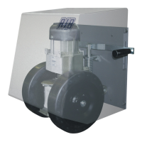
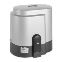
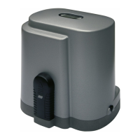
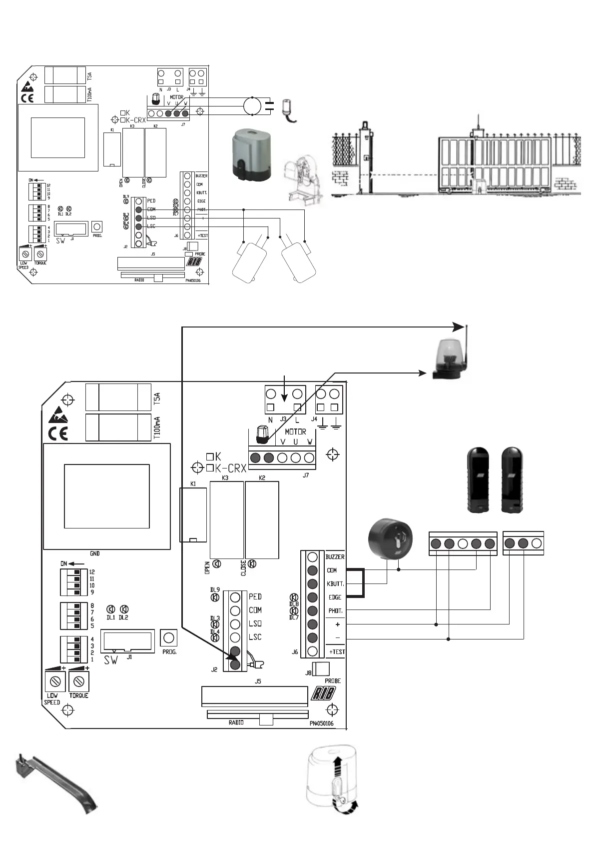
SIMPLIFIED INSTRUCTIONS FOR K800-1400-2200 WITH K2007-CRX
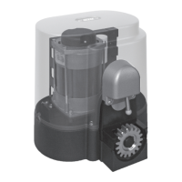
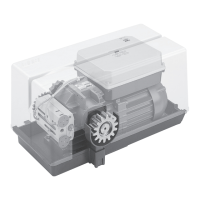
1° Connecting the motor and limit switch (done in the factory)
M
BROWN
BLUE
BLUE
BLACK
C C
NO NO
NC NC
MOTOR
CAPACITOR
A
A
A
The motor is set to open towards the right.
If opening is to the left, the LSO and LSC wires on terminal block J2 and the V
and W wires on terminal block J7 must be reversed.
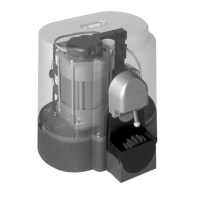
2° Connecting the accessories
ELECTRICAL SUPPLY
quick connector
Press. Insert the wire.
Release to lock it.
ANTENNA – Use an RG58 co-axial cable
Jumper
COM-EDGE
A*A => A+A- Observe the polarity
of the photocells’ electrical supply
A*
A
SC
NC
A*
A
S
A
A
A
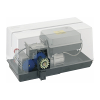
3° Installing and adjusting the limit plate cams
Position the cams on the rack.
Tighten the two screws to lock them. How to finely adjust cam
intervention is explained below.
Release the motor (turn the key counter clockwise until the limit is
reached without forcing) and move the gate by hand
Check when the cams are activated.
Note: The cams must press the electric microswitches before the mobile
part touches the mechanical stops.
IMPORTANT
 Loading...