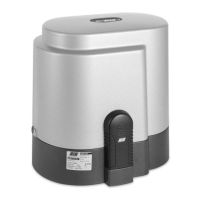
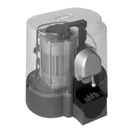
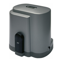
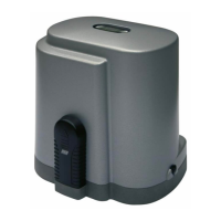
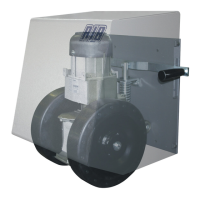
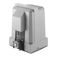
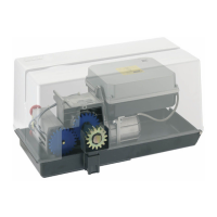
EasyManua.ls Logo

RIB K2007 User Manual

RIB K2007
56 pages
Go to English
To Next Page IconTo Next Page
Page #1 background imageLoading...
Page #1 background image
K800
K1400
K2200
Con funzionamento a uomo presente se le fotocellule o le coste sono guaste.
Conforme alle normative in vigore.
Avec travail avec homme present, dans le cas de panne de sécurité. Conforme
aux Normes en vigueur.
With functioning in dead man mode when the safety devices are failing.
According to current European Norms.
Mit arbeit im mannsbeisein im fall eines ausfalls der Sicherheiten. In
Übereinstimmung mit der aktuellen Normen.
Con funcionamiento a hombre presente en caso de averías con los accesorios
de seguridad. En conformidad a las Normas en vigor.
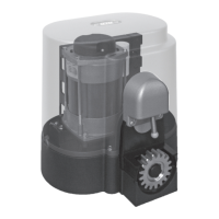
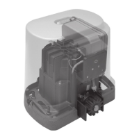
Operatore
Operateur
Operator
Torantrieb
Operador
Alimentazione
Alimentation
Power Supply
Stromspannung
Alimentacion
Peso max cancello
Poids maxi portail
Max gate weight
Max Torgewicht
Peso máx verja
Spinta max
Poussée maxi
Max Thrust
Max Schubkraft
Max Empuje
Coppia max
Couple maxi
Max torque
Max. Drehmoment
Coppia max
Codice
Code
Code
Code
Codigo
K800
230V 50/60Hz
800 kg / 1766 lbs
60 kg / 132 lbs 20,4 Nm AA30039
120V 60Hz 51,4 kg / 113 lbs 17,5 Nm AA30042
K1400
230V 50/60Hz
1400 kg / 3090 lbs
79 kg / 173,8 lbs 27 Nm AA30044
120V 60Hz 88 kg / 193,6 lbs 30 Nm AA30047
K2200
230V 50/60Hz
2200 kg / 4856 lbs
115 kg / 253 lbs 39 Nm AA30049
120V 60Hz 117,5 kg / 258,5 lbs 40 Nm AA30052
ITALIANO pag. 05 / FRANÇAIS pag. 15 / ENGLISH page 25 / DEUTSCH pag. 35 / ESPAÑOL pag. 45
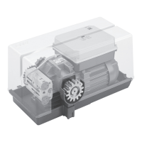
con / avec / with / mit K2007

Questions and Answers:

RIB K2007 Specifications

General IconGeneral
BrandRIB
ModelK2007
CategoryGarage Door Opener
LanguageEnglish

Summary

Important Safety Instructions

Installation Safety Guidelines

Comprehensive steps for safe installation, covering personnel, risk analysis, wiring, controls, and power disconnection.

Instruction Retention and Electrical Safety

Guidelines for keeping instructions and ensuring electrical protection, cable selection, photocell positioning, and safety force limits.

System Overview and Technical Specifications

System Lay-Out Diagram

Visual representation of system components with numbered labels for identification.

Technical Data and Features

Detailed specifications and operational characteristics for K800, K1400, and K2200 models.

Installation Guide

Pre-Installation Checks

Essential checks before installation to ensure gate condition and component readiness.

Motor and Rack Fitting

Instructions for mounting the motor and rack, including height adjustment and clearance.

Limit Switch and Stopper Installation

Guidance on fitting limit switches and mechanical stoppers for gate travel control.

Routine Maintenance

Procedures for periodic maintenance of the gate operator.

Electrical Configuration and Settings

Control Board Connections

Detailed diagram and identification of terminals for wiring the control board.

DIP Switch Settings

Configuration of operating modes, automatic closing, and safety features using DIP switches.

Motor Adjustment and Brake Control

Setting motor torque, low speed, and electronic brake for optimal gate operation.

Operational Programming

Motor Rotation and Limit Check

Procedure to check and set the correct motor rotation direction and gate travel limits.

Gate Operation Programming

Steps for programming complete opening, pedestrian opening, and automatic closing times.

Radio Code Programming

Instructions for adding, deleting, and managing radio transmitter codes.

Functional Operation of Accessories and Safety

Control Accessories Operation

How step-by-step and automatic commands from buttons and remotes function.

Safety Accessories Functionality

Operation of photocells, safety strips, alarms, and dead man mode for safety.

Clock and Pedestrian Mode Usage

Using the clock function for timed opening and the pedestrian button for partial access.

Troubleshooting and Final Assembly

Fault Diagnosis and Solutions

A guide to identifying common faults and applying corrective measures.

Final Assembly Steps

Procedures for fitting the gasket, closing the motor case, and preparing for operation.

Optional Accessories

Photocells and Columns

Details on FIT SLIM and FIT SYNCRO photocells, columns, and transmitters.

Other System Accessories

Information on rack modules, touch sensors, radio transmitters, and probes.

Wireless Devices

Wi-Fi Receiver and Control Systems

Overview of Wi-Fi receiver cards, wireless photocells, and numeric coders.

Wireless Transmitters and Indicators

Details on wireless key selectors, blinkers, and radio transmitters.

Related product manuals