29
J7
R1
J6
J8
J5J2R2 J1
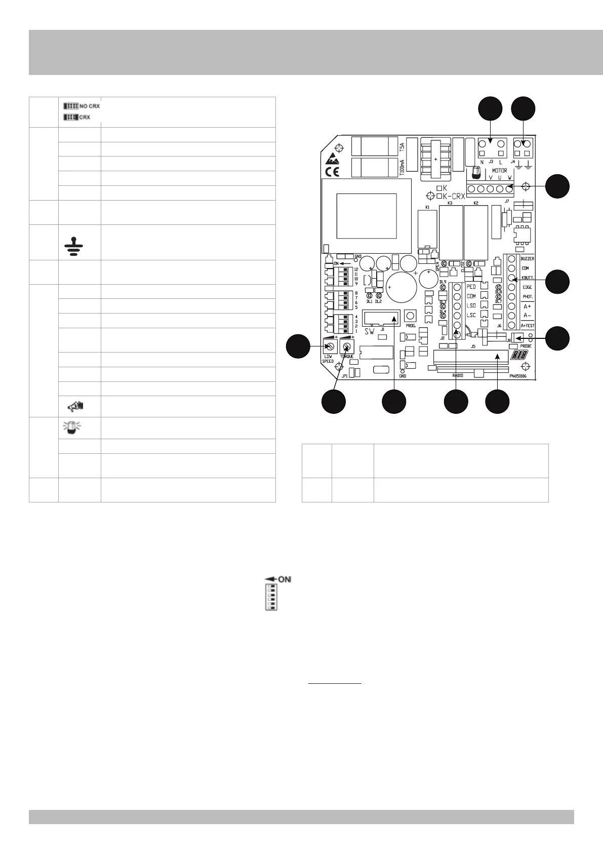
POINT A - ELECTRIC CONNECTIONS
G
B
J1 DO NOT REMOVE ANY JUMPER! OTHERWISE THE
OPERATOR WILL NOT WORK!
J2 AERIAL Radio Antenna
LSC Close limit-switch that cuts off the motor in closing
LSO Open limit-switch that cuts off the motor in opening
COM Limit-switch common contact
PED BUTT Pedestrian opening contact (NO)
J3 L-N Main power supply 230 Vac 50/60 Hz (120V/60Hz upon
request)
J4 EARTH
Connection of the earth line
J5 RADIO Built-in radio module (model CRX),
or connector for radio receiver RIB, 24Vdc supply
J6 A+ TEST 24Vdc safety strip self-test power supply
A+ Accessories power supply +24Vdc
A- Accessories power supply -24Vdc
COM + Common contact (common line for all the command and
safety inputs) (+)
K BUTT. Single pulse contact (NO)
PHOT. Photocells contact (NC)
EDGE Safety strip contact (NC)
-
Buzzer contact (24Vdc max 200 mA) (-)
J7
Flashing light (max 40W )
U - MOTOR Motor common connection
V-W -
MOTOR
Motor phase and capacitor connections
J8 PROBE Temperature sensor cable connection PROBE (Code
ACG4665 optional)
R1 TRIMMER
LOW
SPEED
Electronic regulator for low speed on approach
R2 TRIMMER
TORQUE
Electronic torque regulator
RELAYS AND MOTOR COMMAND
K1 => Flashing light command
K2 => Closing command
K3 => Opening command
Q1 => TRIAC - Motor command in opening and closing
POINT B - SETTINGS
DIP 1 MOTOR ROTATION DIRECTION CHECK (See Point C)
DIP 2 PROGRAMMING (See Point D)
DIP 2-1 PROGRAMMING OF THE PEDESTRIAN OPENING (See Point D)
DIP 1-2 STORAGE/DELETION OF RADIO CODES FOR COMPLETE OPENING
(DIP 1 ON followed by DIP 2 ON) (POINT F) ONLY FOR CRX MODELS
DIP 1-3 STORAGE/DELETION OF RADIO CODES FOR PEDESTRIAN OPENING (DIP 1 ON
followed by DIP 3 ON) (POINT G) ONLY FOR CRX MODELS
OPERATING MODE SETTINGS
DIP 3 ON - Automatic Closing ENABLED
OFF - Automatic Closing DISABLED
DIP 4 ON - Photocells active only in closing
OFF - Photocells always active
DIP 5 ON - blinker pre-flashing
OFF - blinker normal-flashing
DIP 6 ON - STEP BY STEP
Single pulse contact (K BUTT)
Pedestrian button (PED BUTT)
Radio Receiver command
OFF - AUTOMATIC
Single pulse contact (K BUTT)
Pedestrian button (PED BUTT)
Radio Receiver command
DIP 7 ON - electronic brake ENABLED
OFF - electronic brake DISABLED
DIP 8 ON - low speed in approaching DISABLED
OFF - low speed in approaching ENABLED
DIP 9 ON - gradual start ENABLED
OFF - gradual start DISABLED
DIP 10 ON - safety strip self-test ENABLED
OFF - safety strip self-test DISABLED
DIP 11 OFF
DIP 12 OFF for K800-K1400
ON for K2200
S1 => PROG. Programming button
TORQUE => R1 Electronic regulator for motor torque
Adjustment of motor torque is carried out using the TORQUE Trimmer which varies the output
voltage to the head/s of the motor/s (turn clockwise to increase torque).
This torque control is activated after 2 seconds form any manoeuvre begging, whereas the
motor is turned on at full power to guarantee the starting at the manoeuvre begging.
PAY ATTENTION: IF THE TORQUE TRIMMER SETTING IS CHANGED, IT IS PREFERABLE
TO REPEAT THE TIME PROGRAMMING.
LOW SPEED => R1 Electronic regulator for low speed on approach
Adjustment of low speed is carried out using the LOW SPEED Trimmer which varies the output
voltage to the head/s of the motor/s (turn clockwise to increase speed). Adjustment is carried
out to establish the correct speed at the completion of opening and closing, depending on the
structure of the gate, or if there is any light friction that could compromise the correct working
of the system. The low speed is activated (DIP8 OFF) when the gate leaf is 0.50-0.60 meters
away from the complete close or open position.
ELECTORNIC BRAKE
If the low speed in approaching is disabled (DIP8 ON), is preferable turn the DIP7 ON to enable