32DSSP01.A
2-4
D. CONTROLS AND INDICATORS
WARNING!
THE LIFT IS ALLOWED TO OPERATE ONLY WHEN VEHICLE MANUFACTURER’S
INTERLOCK CIRCUITRY IS ACTIVATED. NEVER ATTEMPT TO OPERATE LIFT
WITH INTERLOCK BYPASSED. REFER TO VEHICLE OWNER/OPERATOR MAN-
UAL FOR INTERLOCK INSTRUCTIONS BEFORE OPERATING LIFT.
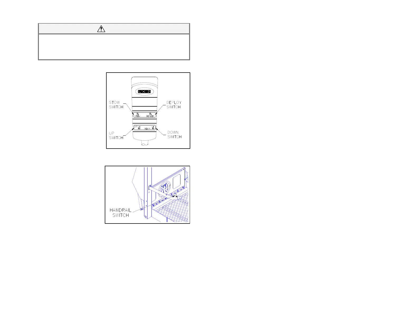
¡ Control Pendant
Refer to Figure 2-5. The lift is con-
trolled with a hand held, hard-wired
remote control pendant. It has two
dual-position rocker switches. The
lift functions are performed by
pushing and holding one end of an
appropriate switch. Pushing DE-
PLOY switch unfolds lift from vehi-
cle and pushing STOW switch folds
platform into vehicle. Pushing
DOWN switch lowers lift towards
ground and pushing UP switch
raises lift towards floor. The pen-
dant is stowed on a wall-clip inside
vehicle.
¡ Handrail switch
Refer to Figure 2-6. The alter-
nate, spring-loaded handrail
switch may be used by platform
occupant to operate UP and
DOWN functions of lift. The
switch is located on the platform
handrail. To perform desired
function, push and hold switch
until function is completed.
FIGURE 2-6: HANDRAIL SWITCH
 Loading...
