32DSSP03.B
2 - 5
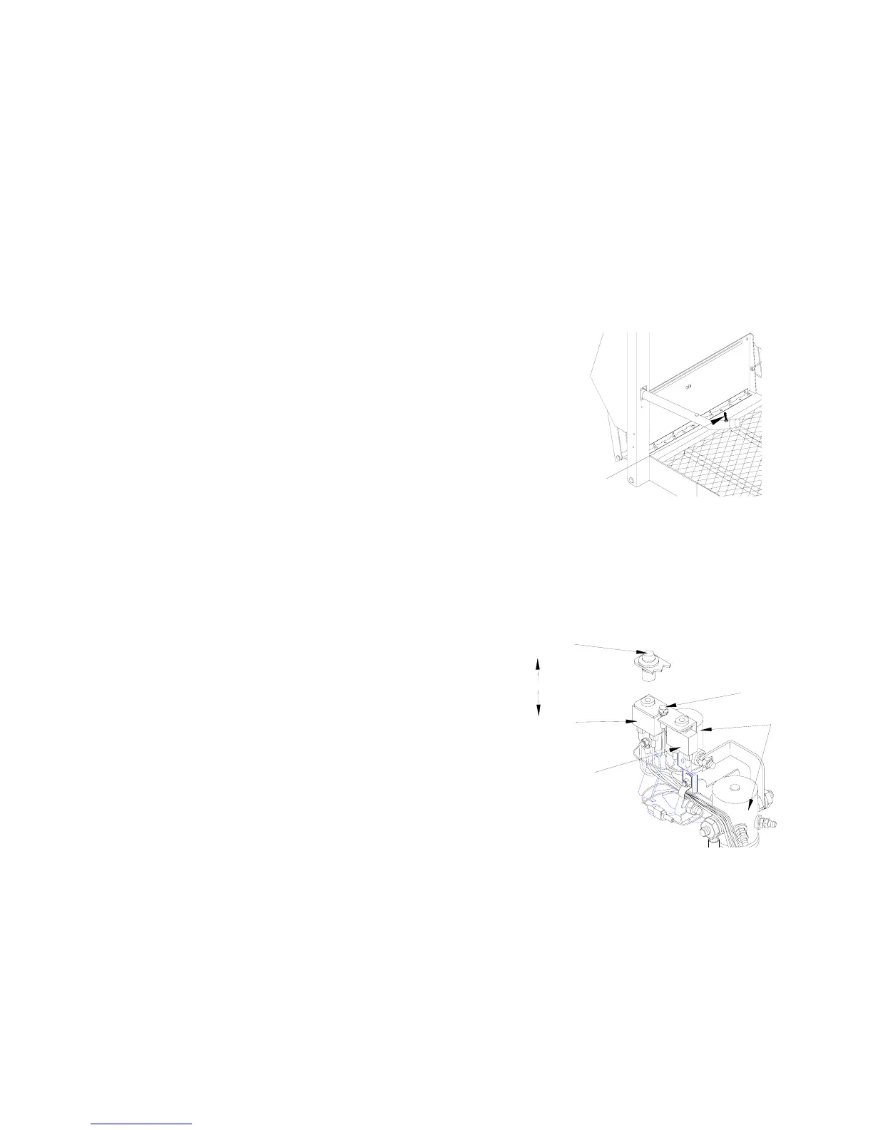
CONTROL SWITCH
Refer to Figure 2-6. An alternate lift control switch is located on the left side platform armrest.
The spring-loaded switch lever can be used by the passenger to control UP and DOWN motions
of the platform. To move platform downward push and hold switch lever forward, and to move
platform upward pull and hold lever back. Release lever at any time to halt motion.
CIRCUIT BREAKERS AND INDICATOR LIGHTS
Interlock Indicator Light
Refer to
Figure 2-7. The purpose of a vehicle interlock system is to prevent operation of lift if
an unsafe condition is present. When a vehicle interlock system is interfaced with the lift cir-
cuitry, the interlock indicator shows whether or not the interlock is operating properly. The
light is interfaced with the electrical system so that regardless of which interlock system is
used, the light will be on when the interlock provides power to lift and off when interlock has
removed power to lift. When there is no interlock system installed, the light stays illuminated
at all times.
CIRCUIT BREAKER
8 AMP CONTROL SYSTEM
30 AMP DOOR OPERATOR
INDICATOR LIGHT
INTERLOCK
CIRCUIT BREAKER
PUMP SOLENOIDS
LED STATUS INDICATOR
OR
FIGURE 2-7: INDICATOR LIGHT, CIRCUIT BREAKERS, AND LED INDICATOR
CONTROL
SWITCH
LEVER
FIGURE 2-6: LIFT CONTROL SWITCH
 Loading...