Do you have a question about the RIDGID 1000RSDSSmart and is the answer not in the manual?
Indicates a potentially hazardous situation that could result in death or serious injury if not avoided.
Observing specific warnings to reduce the risk of electric shock during installation and use.
Ensures connection only to properly grounded receptacles to reduce shock risk.
Receptacle should be protected by a ground fault circuit interrupter for added safety.
Never remove the ground prong or bypass grounding wires.
Ensure power supply has a fuse or breaker rated for the pump's current.
Do not remove power cord or connect conduit directly to the pump.
Always disconnect the pump from power supply before servicing or adjustments.
Avoid walking on wet floors until power is off; call electrician if panel is in basement.
Avoid wet conditions, flammable fluids, and non-potable water use.
Do not use extension cords or surge protectors; contact electrician for new receptacle.
Ensure switch operation is unobstructed; test pump after installation.
Use rigid piping and fittings to secure pump and prevent movement.
Use a check valve to prevent back-flow of water after each pump cycle.
Do not install or operate the pump if it has been damaged in any way.
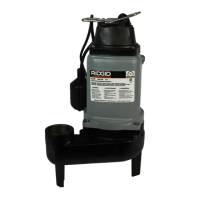
Do not lift pump by power cord or air tube; use handle or lift ring.
Do not use pump with mud, sand, cement, oil, chemicals, grey water, or raw sewage.
Use an independent alarm or backup pump for high water risk.
Product may expose users to chemicals known to cause cancer and reproductive harm.
Air switch is not adjustable; modifications void warranty and may cause premature failure.
Equipment tested and found to comply with Class B digital device limits for residential installations.
Maintain 20 cm separation for mobile transmitting devices and comply with antenna gain limits.
Installation must comply with National Electric Code and all applicable local codes and ordinances.
Use a basin or pit large enough to accommodate the pump.
Clean the basin/pit of all debris before installation.
Place pump directly on bottom of basin on a solid, level surface; use brick or block if needed.
Install discharge plumbing per codes; use rigid PVC pipe, no flex hosing.
Install a check valve to prevent back-flow; position above basin for easy removal.
Install a gate valve or ball valve if required by local, regional, or state code.
Connect pump power supply cord to a ground fault circuit interrupter (GFCI) receptacle.
Fill basin/pit with water; pump activates when water reaches level 4 on controller.
Pump stops when water level reaches the switch-off level.
Verify discharge pipe carries water away from foundation; ensure downward slope for drainage.
Secure basin cover and gasket to prevent debris, injury, and contain odors.
Follow instructions on the next page for device activation.
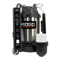
Guide to LED colors (Green, Yellow, Red) and their corresponding symptoms and remedies.
Actionable guide for Mute Alarm, System Test, Reboot, and Reset functions via controller buttons.
Download SmartSumpbyRIDGID App, open, and click '+ Add Device' to begin activation.
Select RIDGID device and verify the status LED is blinking yellow.
Allow camera access and scan the QR code on the device for automatic detection.
Select network, enter password, and connect to Wi-Fi for device registration.
Enter zip code to link local weather data with pump data for future analysis.
Always disconnect the pump from the power supply before installing, servicing, or making adjustments.
Let pump cool for a minimum of 2 hours before attempting service due to hot oil.
Pump bearings are permanently lubricated; dielectric oil for cooling can be harmful to the environment.
Motor has auto-reset thermal protector; tripping indicates overload or end of product life.
Addresses issues like low water level, blown fuse, motor problems, or switch obstruction.
Covers causes like back-flow from discharge pipe or switch issues.
Troubleshoots thermal overload protection trips due to temperature, switch, or obstructions.
Addresses potential issues with the GFCI outlet or the pump itself.
Covers causes like worn bearings, broken impeller, or rigid piping attachments.
Troubleshoots switch issues, obstructions, or improper pump sizing.
Addresses low voltage, clogged inlet, broken impeller, or improper sizing.
Inspect pump 3-4 times per year for movement or debris; lack of maintenance voids warranty.
Ensure pump is plugged into working GFCI outlet; check and reset GFCI if tripped.
Ensure pump is standing upright; vibrations can cause it to tilt.
Pour water into pit to test automatic start and drainage; service if pump doesn't start.
Check and clear the inlet screen of any small stones or debris.
Silences alarm for 12 hours; custom mutes available via companion app.
Allows manual initiation of system tests via controller or companion app.
Performs a device reboot to reset its current state.
Re-establishes Wi-Fi connection without losing personalized settings or data.
Resets pump to factory settings and reboots; recommended via companion app.
Five-year warranty for repair or replacement of defective parts or workmanship.
Excludes damage from accident, abuse, misuse, neglect, improper installation, or maintenance.
Requires retaining purchase receipt and contacting RIDGID Pumps for return authorization.
| Brand | RIDGID |
|---|---|
| Model | 1000RSDSSmart |
| Category | Water Pump |
| Language | English |