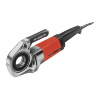
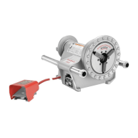
The RIDGID 600-I/690-I Power Drives are robust, double-insulated tools designed to provide power for threading pipe and conduit. These power drives are essential for professionals who require a reliable and efficient method for creating threads on various pipe sizes. The forward and reverse rotation of the tool can be easily selected using a slide switch, offering flexibility and control during operation. The ON/OFF function is managed by a two-step momentary contact switch, ensuring user safety and precise control over the tool's power.
The 600-I Power Drive is specifically engineered to work with RIDGID 11-R Drop Head Die Heads, accommodating pipe sizes from 1/8" to 1 1/4". For larger applications, the 690-I Power Drive extends the threading capacity to 2" pipe, also utilizing RIDGID 11-R Drop Head Die Heads. When using the 690-I for smaller pipe sizes (1/8" – 1 1/4"), an adapter is required. Both the adapter and the larger 1 1/2" - 2" die heads are securely held in the 690-I Power Drive by a specialized retaining mechanism.
Before each use, a thorough pre-operation inspection is crucial to ensure safe and proper functioning. Users should always confirm that the power drive is unplugged before any inspection or adjustment. It's important to clean any oil, grease, or dirt from the power drive and its support device, including the handles and controls, as this helps prevent slipping and aids in inspection. The power drive and support arm should be checked for any damage, modifications, or misaligned/binding parts. The ON/OFF switch and F/R slide switch must operate correctly. The support arm's gripping teeth should be clean and in good condition, and all warning labels must be present and readable. Additionally, the cutting edges of the dies should be inspected for wear, deformation, or chips, as dull or damaged dies can lead to poor quality threads and increased risk of injury. Any other equipment used in conjunction with the power drive should also be maintained and inspected according to its instructions.
Proper setup and operation are paramount for safety and effective threading. The work area should be well-lit, clear of flammable materials, and provide a stable, dry surface for the equipment and operator. Good ventilation is recommended, and the tool should not be used extensively in small, enclosed areas. The electrical outlet must be properly wired and of the correct voltage, with a clear path for the power cord. The pipe to be threaded should be inspected, squarely cut, and deburred to prevent die damage and ensure proper engagement.
When installing die heads, ensure the ON/OFF switch is released and the power drive is unplugged. For the 690-I, the drive ring is rotated counter-clockwise to open the retaining mechanism, allowing the die head or adapter to be fully inserted. Releasing the drive ring confirms the secure placement. For smaller die heads on the 600-I, the octagonal end of the 11-R Die Head is inserted until secured by the spring ring. The F/R slide switch should be positioned for the desired right or left-hand thread.
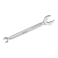
Resisting threading forces is a critical aspect of operation. The supplied support arm (601 or 602 for 600-I, 691 or 692 for 690-I) should always be used unless space constraints prevent it. The support arm clamps to the pipe, helping to resist threading forces. It should be positioned so its end aligns with the pipe and its top is horizontal, which correctly places the arm for threading and prevents oil from entering the motor. The support arm jaws must be squarely aligned and securely tightened. If the support arm cannot be used, other support devices must be employed, such as bracing the power drive's gear or fan housing against a structural member. The pipe and surroundings must be able to withstand the tool's weight and threading forces.
During threading, the power drive should be plugged in with dry hands. The die head is positioned over the pipe end, and the power drive is supported as directed. The ON/OFF switch is actuated simultaneously with a push against the die head cover plate to start the thread. It is crucial to avoid wearing gloves, jewelry, or using a rag while pushing on the cover plate to prevent entanglement. Once the dies engage, they will pull themselves onto the pipe. A generous quantity of RIDGID Thread Cutting Oil should be applied to the threaded area to reduce torque, improve thread quality, and increase die life. The ON/OFF switch is depressed until the pipe end is even with the dies, then released. To remove the die head, the F/R slide switch is reversed, and the ON/OFF switch is actuated, holding the handle firmly to resist forces while backing off.
After threading, the threads should be inspected visually for smoothness, completeness, and proper form. Issues like tearing or thin threads may indicate problems that need addressing. The thread size should be checked with a ring gauge, ensuring the pipe end extends through the gauge within one turn. If a ring gauge is unavailable, a new, clean fitting can be used to gauge the thread size, aiming for 4 to 5 turns to hand-tight engagement for NPT threads and 3 turns for BSPT threads.
Maintenance is essential for the longevity and safe operation of the power drive. After each use, threading chips should be emptied from the 418 Oiler chip tray, and any oil residue wiped off. The power drive, including handles, controls, and the 690-I retaining mechanism, should be cleaned of oil, grease, chips, or dirt. The support arm and die heads also require cleaning.
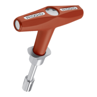
Dies in 11-R Die Heads can be changed by removing four screws from the cover, taking off the cover plate, and removing the old dies. New dies are inserted into slots, ensuring the numbered edge is up and corresponds with the die head slots. Dies must always be replaced as a set. After replacing the cover plate and lightly tightening the screws, the die head is placed on an already threaded pipe until the dies begin to thread, which forces the stop on the dies outward and properly sets the size. The four screws are then securely tightened.
Motor brushes should be checked every 6 months and replaced if worn to less than 5/16" (8 mm). To replace brushes, the machine is unplugged, brush caps are unscrewed, and brushes are removed for inspection. After re-installing new brushes and securely tightening the caps, it's good practice to run the unit at idle for 15 minutes in both forward and reverse directions to seat the brushes to the commutator.
When storing the machine, it should be kept indoors, well-covered, and out of reach of children and untrained users. Any service or repair beyond routine maintenance should be handled by an authorized RIDGID service technician or returned to the factory. Threading oil information can be found on the container labels and Material Safety Data Sheet (MSDS). For disposal, parts of the power drives can be recycled, and components should be disposed of in compliance with local regulations. For EC countries, electrical equipment should not be disposed of with household waste but collected separately and disposed of in an environmentally correct manner.