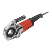
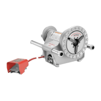
NOTE! Installation can be made into either side of the
Power Drive.
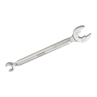
Figure 2 – Installing No. 11-R Drop Head Die Head
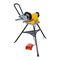
2. If possible, secure the pipe in a portable tristand vise
or a bench vise.
To prevent tipping, long lengths of pipe
should also be supported with pipe stand.
3. Be sure the 418 Oiler is properly filled with RIDGID
Thread Cutting Oil. Position the oiler in front of the
vise.
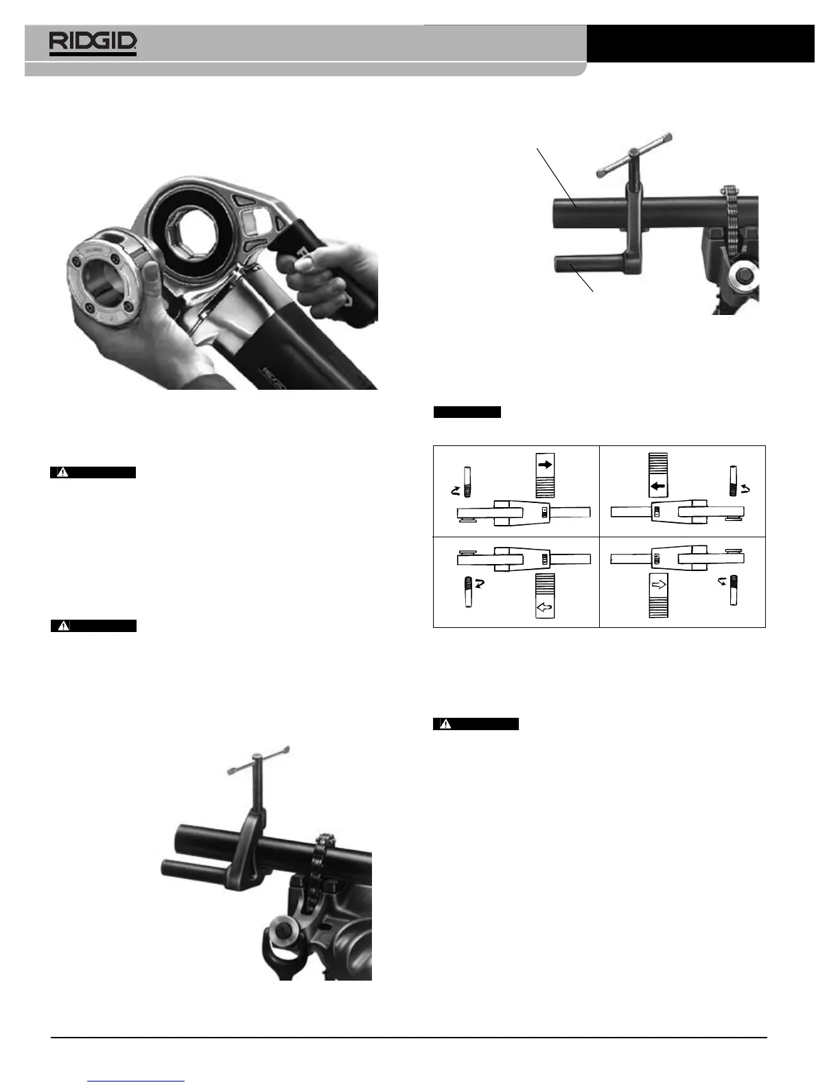
4. Position No. 601 Support Arm on pipe so end of
torque arm is in line with end of the pipe
(Figures 3
& 4).
To avoid serious injury from losing control
of the Power Drive, a support arm should be used when
threading
3
/
4
″ or larger pipe.
When threading pipe less than
3
/
4
″ in size without a
support arm, hold onto the Power Drive firmly with
one hand to exert pressure against the handle forces
developed during threading.
5. Position the directional switch for the desired right or
left hand thread
(Figure 5)
.
Change position of the directional switch
only when the motor is switched OFF.
6. Place Die Head over end of pipe.
To avoid serious injury, make sure Power
Drive is correctly positioned on support arm. For right
hand threads, die head will rotate clockwise (looking
at the face of the Die Head). Forces developed by the
threading torque will be in the opposite or counter-clock-
wise direction.
7. Simultaneously actuate the ON/OFF switch and exert
pressure against the Die Head with the palm of free
hand to make sure thread is started. Apply plenty of
thread cutting oil to the dies during threading. This will
reduce the torque required to thread and improve
the thread quality
(Figure 6)
.
8. Keep ON/OFF switch depressed until end of the pipe
is even with edge of the dies and release the switch
button.
Ridge Tool Company6
600 Power Drive
Figure 3 – Using No. 601 Support Arm when threading
3
/
4
″ pipe and larger
Figure 4 – Positioning No. 601 Torque Arm in Line with
End of Pipe
Pipe
Torque Arm
A. Right Hand Thread B. Left Hand Thread
Figure 5 – Direction Change Switch/Die Head
Orientation.
WARNING
CAUTION
WARNING
WARNING