920 Roll Groover
Ridge Tool Company16
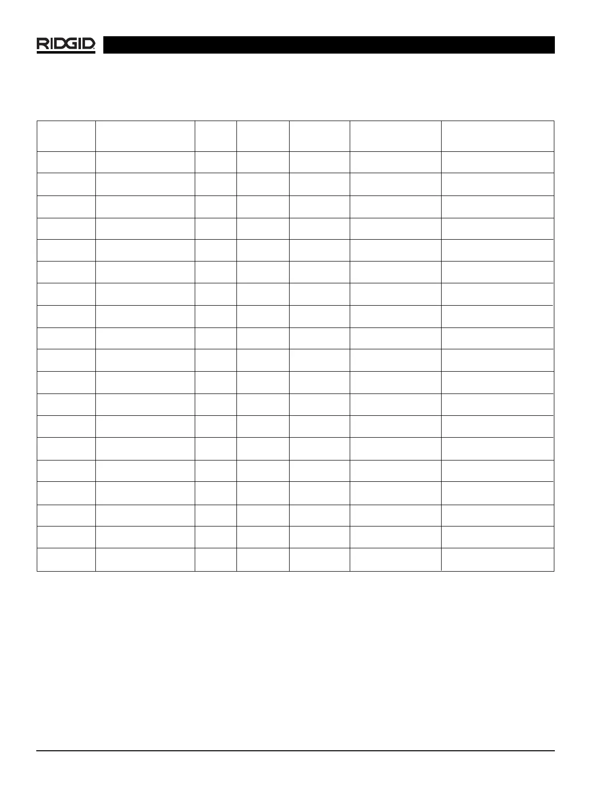
Table I. Standard Roll Groove Specifications
1
NOTE! All Dimensions are in Inches.
NOM. PIPE MIN. GASKET GROOVE GROOVE NOM.
PIPE DIAMETER WALL SEAT WIDTH DIAMETER GROOVE DEPTH
SIZE O.D. TOL. THK. +.015/-.030 +.030/-.015 O.D. TOL. REF
2
1 1.315 +.013 .065 .625 .281 1.190 +.000 .063
-.013 -.015
1
1
/
4
1.660 +.016 .065 .625 .281 1.535 +.000 .063
-.016 -.015
1
1
/
2
1.900 +.016 .065 .625 .281 1.775 +.000 .063
-.016 -.015
2 2.375 +.024 .065 .625 .344 2.250 +.000 .063
-.016 -.015
2
1
/
2
2.875 +.030 .083 .625 .344 2.720 +.000 .078
-.018 -.015
3 3.50 +.030 .083 .625 .344 3.344 +.000 .078
-.018 -.015
3
1
/
2
4.00 +.030 .083 .625 .344 3.834 +.000 .083
-.018 -.015
4 4.50 +.035 .083 .625 .344 4.334 +.000 .083
-.020 -.015
5 5.563 +.056 .109 .625 .344 5.395 +.000 .084
-.022 -.015
6 6.625 +.050 .109 .625 .344 6.455 +.000 .085
-.024 -.015
8 8.625 +.050 .109 .750 .469 8.441 +.000 .092
-.024 -.020
10 10.75 +.060 .134 .750 .469 10.562 +.000 .094
-.025 -.025
12 12.75 +.060 .156 .750 .469 12.531 +.000 .110
-.025 -.025
14 14.00 +.060 .156 .938 .469 13.781 +.000 .110
-.025 -.025
16 16.00 +.060 .165 .938 .469 14.781 +.000 .110
-.025 -.025
18 18.00 +.060 .165 1.000 .469 17.781 +.000 .110
-.030 -.025
20 20.00 +.060 .188 1.000 .469 19.781 +.000 .110
-.030 -.025
22 22.00 +.060 .188 1.000 .500 21.656 +.000 .172
-.030 -.025
24 24.00 +.060 .218 1.000 .500 23.656 +.000 .172
-.0230 -.025
1. As per AWWA C606-87
2. Nominal Groove Depth is provided as a reference dimension. Do not use groove depth to determine acceptability.
NOTE! Fitting manufacturer’s recommendations should be followed regarding Maximum Allowable Flare Diameter.
 Loading...