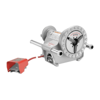
920 Roll Groover
Ridge Tool Company 17
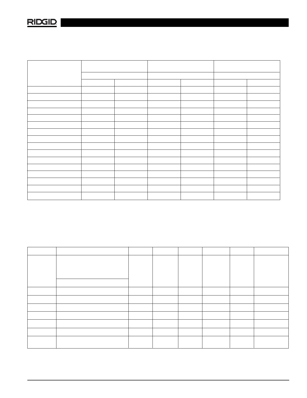
CARBON STEEL OR STAINLESS STEEL
ALUMINUM PIPE OR TUBE PIPE OR TUBE PVC PIPE
Pipe Size Wall Thickness Wall Thickness Wall Thickness
Min. Max. Min. Max. Min. Max.
2″ .065 .154 .065 .154 .154 .154
2
1
/
2
″ .083 .203 .083 .203 .203 .276
3″ .083 .216 .083 .216 .216 .300
3
1
/
2
″ .083 .226 .083 .226 .226 .318
4″ .083 .237 .083 .237 .237 .337
5″ .109 .258 .109 .258 .258 .258
6″ .109 .280 .109 .280 .280 280
8″ .109 .322 .109 .322 .322 .322
10″ .134 .365 .134 .365 — —
12″ .156 .406 .156 .406 — —
14″ .156 .375 .156 .375 — —
16″ .165 .375 .165 .375 — —
18″ .165 .250 .165 .250 — —
20″ .188 .250 .188 .250 — —
22″ .188 .250 .188 .250 — —
24″ .218 .250 .218 .250 .— —
Table II. Pipe Maximum and Minimum Wall Thickness
NOTE! All Dimensions are in Inches.
12345678
ABCD T
Nom. Tubing Outside Gasket Groove Groove Nominal
1
Min. Max.
Size Diameter O.D. Seat Width Dia. Groove Allow. Allow.
Inches A +.03 +.00 Depth Wall Flare
Basic Tolerance ±.03 –.00 –.02 Thick. Dia.
2″ 2.125 ±0.002 0.610 0.300 2.029 0.048 0.064 2.220
2
1
/
2
″ 2.625 ±0.002 0.610 0.300 2.525 0.050 0.065 2.720
3″ 3.125 ±0.002 0.610 0.300 3.025 0.050 0.045 3.220
4″ 4.125 ±0.002 0.610 0.300 4.019 0.053 0.058 4.220
5″ 5.125 ±0.002 0.610 0.300 5.019 0.053 0.072 5.220
6″ 6.125 ±0.002 0.610 0.300 5.999 0.063 0.083 6.220
8″ 8.125 +0.002 0.610 0.300 7.959 0.088 .109 8.220
-0.004
Table III. Copper Roll Groove Specifications
NOTE! All Dimensions are in Inches.
1. Nominal Groove Depth is provided as a reference dimension. Do not use groove depth to determine groove acceptability.
 Loading...