Do you have a question about the RIDGID R860052 and is the answer not in the manual?
| Voltage | 18V |
|---|---|
| Battery Type | Lithium-Ion |
| Chuck Size | 1/2 inch |
| Max Torque | 750 in-lbs |
| Speed Settings | 2 |
| Brushless Motor | Yes |
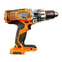
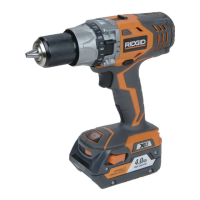
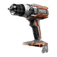
| Type | Cordless Drill/Driver |
| No Load Speed | 0-550 / 0-1, 900 RPM |
Keep work area clean, avoid explosive atmospheres, and keep bystanders away.
Match plugs, avoid grounded surfaces, protect from wetness, and care for cords.
Stay alert, use common sense, wear PPE, prevent unintentional starting, and maintain balance.
Use correct tool, ensure switch function, disconnect power for adjustments, store safely, and maintain tools.
Use specified chargers and battery packs, store away from metal, and handle leakage properly.
Avoid fire/heat, do not damage, prevent explosion, charge correctly, and store in moderate temperatures.
Use auxiliary handles, insulated grip, know your tool, wear proper PPE, and handle battery tools safely.
Defines DANGER, WARNING, CAUTION, and NOTICE for risk communication.
Explains symbols for Safety Alert, Read Manual, Eye Protection, Wet Conditions, and Recycle.
Defines symbols for Volts, Minutes, Direct Current, No Load Speed, and Per Minute.
Do not use if not fully assembled or if parts are missing/damaged. Do not modify product.
Avoid carelessness, remove battery pack during adjustments, wear eye/hearing protection, use recommended accessories.
Suitable for drilling wood, ceramics, plastics, fiberglass, laminates, metals, and driving screws.
Controls drill speed by trigger pressure; release to stop. Whistling noise is normal.
Selects forward, reverse, or center lock. Push fully for drill to run.
Lock switch, insert pack until latches snap, depress latches to remove.
Use keyless chuck, do not use a wrench. Insert bit straight and tighten.
Select LO (1) for high torque, HI (2) for fast drilling. Never change speeds while running.
Rotate adjustment ring to set torque for screw size and material type.
Move bit into workpiece with light pressure. Prepare for binding and use center punch on hard surfaces.
Use high speed steel bits, select drilling mode. Use light oil for metal drilling.
Avoid solvents on plastic parts. Use clean cloths to remove dirt, dust, oil, and grease.
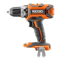
Identifies parts like torque adjustment ring, gear train, rotation selector, bit storage, trigger, and chuck.
Illustrates selector for forward, reverse, and lock positions.
Shows how to depress latches to release the battery pack.
Illustrates correct and incorrect methods for locking and unlocking the chuck jaws.
Highlights wrong method for inserting a drill bit into the chuck.
Illustrates the Hi-Lo speed selector for different applications.
Shows the adjusting ring for setting torque and how to increase/decrease it.
Demonstrates correct technique for drilling and driving screws.
Warns about chemicals including lead, silica, arsenic, and chromium in product dust.
Recommends working in ventilated areas and using approved safety equipment like dust masks.
Provides contact details for parts, service, and locating authorized service centers.
Fields for Model No. and Serial No. for service inquiries.