- 23 -
COMMUNICATION INTERFACE
R.E.P.O.
R.E.P.O.
This isolated input is used to turn the CSS off remotely in case of an emergency.
The CSS is supplied from the factory with the “Remote Emergency Power Off” (R.E.P.O.) terminals short-circuited (refer to "CSS
DETAILS” ref.7). If it is to be installed, remove the short-circuit and connect to the normally closed contact of the stop device using a
double insulated cable.
In case of emergency, by activating the stop device, the R.E.P.O. control is opened, and the CSS will shut-down (refer to USER
MANUAL), and the load will be powered off completely.
The R.E.P.O. circuit is self-powered using a SELV type circuit. No external power supply voltage is therefore required. When it is
closed (normal condition), a maximum current of 15mA is present.
NOTE: If more than one CSS is to be conected within the same R.E.P.O system. Each CSS must be provided with its own dedicated
separate set of contacts. Do not connect the systems in parallel or series.
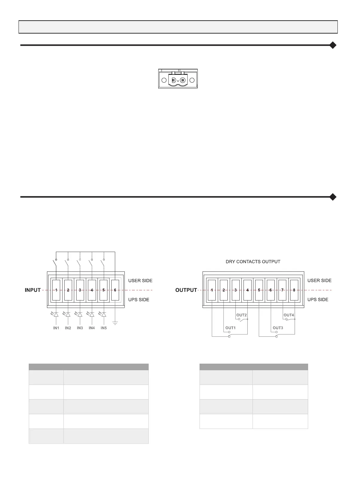
PROGRAMMABLE IN – OUT SIGNALS
The IN-OUT signals (refer to "CSS DETAILS” ref. 7) have a standard factory configuration. The only input signal enabled is “IN 5”; the
other signals must be enabled from the display panel.
For further information refer to the “User Manual”.
Moreover all the signals can be programmed using the service configuration software reserved to service personnel only.
FACTORY DEFAULT SETTING
INPUT FUNCTION
IN 1 # Position of the External SWMB
IN 2 # Position of the External SWOUT
IN 3 # CB OFF
IN 4 # Bypass ON
IN 5 System ON
# These inputs must be enabled from the display panel
FACTORY DEFAULT SETTING:
OUTPUT FUNCTION
OUT 1 Battery low
OUT 2 Battery working
OUT 3 System OK
OUT 4 Battery circuit alarm
The output dry contacts are rated to:
1A @ 24Vdc or 1A @ 30Vac
NOTE: In case of an external maintenance bypass or Battery Cabinet installation, the relative switch auxiliary contacts must be
connected to these inputs and programmed.