- 5 -
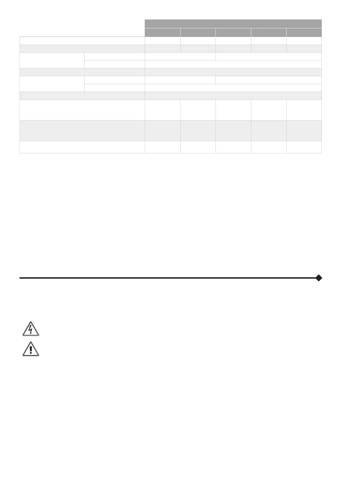
ELECTRICAL INFORMATION TABLE
Table 2
6 kVA 8 kVA 10 kVA 15 kVA 20 kVA
Power [kVA / kW] 6/6 8/8 10/10 15/15 20/20
Power according to EN 50171 [kW]
5 6 8 12 16
V Input [V]
Three-phase (CBT / CBM)
N/A 400 ± 20% (3PH + N)
Single-phase (CBM) 230 ± 20% (PH + N)
Frequency Input [Hz]
50 - 60
V Output [V]
CBT
N/A 380-400-415 (3PH + N)
CBM 220-230-240 (PH + N)
Frequency Output [Hz]
50 / 60
Power dissipated @ 100% triphase load
(1)
N/A N/A
0.41 kW
350 kCal/h
1400 B.T.U./h
0.59 kW
505 kCal/h
2000 B.T.U./h
0.84 kW
720 kCal/h
2860 B.T.U./h
Power dissipated @ 100% single-phase load
(1)
0.26 kW
224 kCal/h
887 B.T.U./h
0.34 kW
292 kCal/h
1160 B.T.U./h
0.44 kW
375 kCal/h
1485 B.T.U./h
0.62 kW
530 kCal/h
2100 B.T.U./h
0.89 kW
765 kCal/h
3030 B.T.U./h
Flow rate of the fans for removing the heat from the
installation room
(2)
(referred to single-phase)
140 m
3
/h 180 m
3
/h 235 m
3
/h 330 m
3
/h 475 m
3
/h
(1) 3.97 BTU / h = 1 kcal / h
(2) To calculate the air flow rate, the following formula may be used: Q [m3/h] = 3.1 x Pdiss [Kcal/h] / (ta - te) [°C]
Pdiss is the power expressed in Kcal/h dissipated by all the devices installed in the installation environment.
ta= ambient temperature, te=outside temperature. To take leaks into account, the value obtained should be increased by 10%.
The table shows an example of a flow rate with (ta - te)=5°C and a rated resistive load (pf=1).
(Note: This formula is applicable if ta>te, only; if the CSS installation does not require an air-conditioning system).
ELECTROMAGNETIC COMPATIBILITY
This CSS product conforms to the current electromagnetic compatibility (EMC) regulations (C2 class). It may cause radio interference
in the home environment. The user may have to adopt supplementary measures.
This product is for professional use in industrial and commercial environments. Connections to USB must be made with the cable
provided; the connection to the RS232 (RJ10 connector) have to be made with shielded cables less than 3 metres long.
OVERVOLTAGE PROTECTION
The CSS has been designed to be powered by an AC mains supply with category 2 voltage spikes. if it connected to an AC supply
with different characteristics or if it is potentially subject to even transitory overvoltage, external protection equipment must be installed
to it.
PRELIMINARY INFORMATION FOR INSTALLATION
ALL OPERATIONS DESCRIBED IN THIS SECTION MUST BE PERFORMED BY QUALIFIED AND
TRAINED PERSONNEL ONLY.
Our Company assumes no liability for damages caused by incorrect connections or operations not described in
this manual.
The following operations have to be performed with the CSS disconnected from the power source, switched off
and with all equipment switches open.
Before making the connection, open all cabinet switches and verify that the CSS is completely isolated from all
power sources: battery and AC power supplies. In particular, check that:
- the CSS input line is completely disconnected
- the CSS bypass line is completely disconnected
- the CSS battery line switch/fuses are open
- all CSS switches are in the open position
- check with a multimeter that there are no dangerous voltages
The first connection to be made is the protective conductor (earth wire), this must be connected to the bolt
marked as PE.
The CSS must only be operated whilst connected to a suitable earthing system.
The input Neutral must always be connected.
ATTENTION: a three-phase 4-wire distribution system is required.
The standard CSS version must be connected to a 3 Phase + Neutral + PE (ground protection) power source.
Ensuring that the incoming phase rotation is within a clockwise direction.
ATTENTION: After the installation operations are completed, refit all of the cabinet protection panels using the
appropriate screws supplied.