3 DESCRIPTION OF THE APPLIANCE
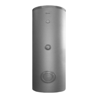
R 7200 V Plus storage cylinders generate and store domestic
hot water, and are available in six models from the 200 to the
1000.
Their most important technical features are:
− the storage cylinder and coil are specially designed
and shaped for optimum performance in terms of
stratication, heat exchange and replenishment times
− internal glazing, bacteriologically inert, to ensure the
maximum hygiene of treated water, reduce limescale
deposits and make cleaning operations easier
− CFC-free polyurethane insulation and an elegant external
casing reduce heat loss
− Temperature sensor and power cables are all internally
routed (models 200 to 550).
− A ange is provided for easy cleaning and maintenance
of the anti-corrosion magnesium anode (double on
models 800 and 1000).
R 7200 V Plus storage cylinders can be equipped with a
dedicated
R control panel (optional accessory) and can be
used in conjunction with all boilers designed for central heating
only.
4 IDENTIFICATION
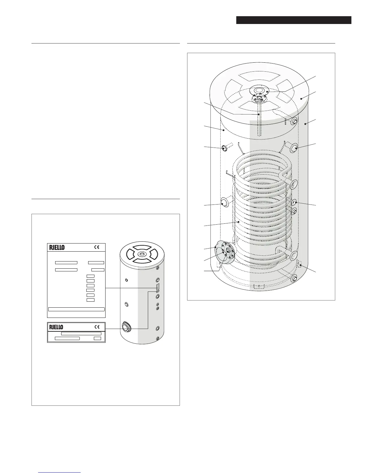
R 7200 V Plus storage cylinders are identied by:
Data plate
This lists the technical specications and performance of the
product.
STORAGE CYLINDER
PUFFERERHITZER
Model
Modell
Serial number
Seriennummer
Code
Year of manufacture
Baujahr
Maximum absorbed power [T° Primary 80°C]
Max. Leistungsaufnahme [T° Primärkreis 80°C]
Operating pressure
Betriebsdruck
Power supply
Stromversorgung
bar
V-Hz
Storage cylinder capacity
Erhitzerinhalt
lt
Serial number
Seriennummer
Model
Modell
kW
066964ED
Obligatory ground connection - Erdschluss ist Vorschrift
Stromaufnahme
W
Electrical consumption
kW
Leistungsaufnahme
Absorbed power
Artikel Nr.
Specific flow rate [∆t 35°C]
Spezifischer Durchfluss [∆t 35°C]
lt/1'
RIELLO S.p.A.
Via Ing.Pilade Riello 7
RIELLO S.p.A.
Via Ing.Pilade Riello 7
37045 Legnago (VR) - ITALY
37045 Legnago (VR) - ITALY
Serial number plate
This species the serial number and model.
9
If these plates or any other means of clearly identifying
the product are defaced, removed or lost, proper
installation and servicing may be rendered difcult.
5 SYSTEM LAYOUT
1 First magnesium anode
2 Storage cylinder
3 Temperature gauge
4 Sleeve for electric heating element (not supplied)
5 Coil
6 Flange cover
7 Cylinder inspection ange
8 Second magnesium anode (only for models 800 and 1000)
9 Adjustable foot
10 Sensor socket
11 Insulation
12 Cover
13 Plug for anode inspection and lifting
(*) On models 800 and 1000, this tting can be used as an
alternative installation position for the rst magnesium
anode (in installations where height is limited).


 To Next Page