20154244
22
Installation
5.13.2 Gas train
Type-approved in accordance with EN 676 and supplied
separately from the burner.
5.13.3 Gas train installation
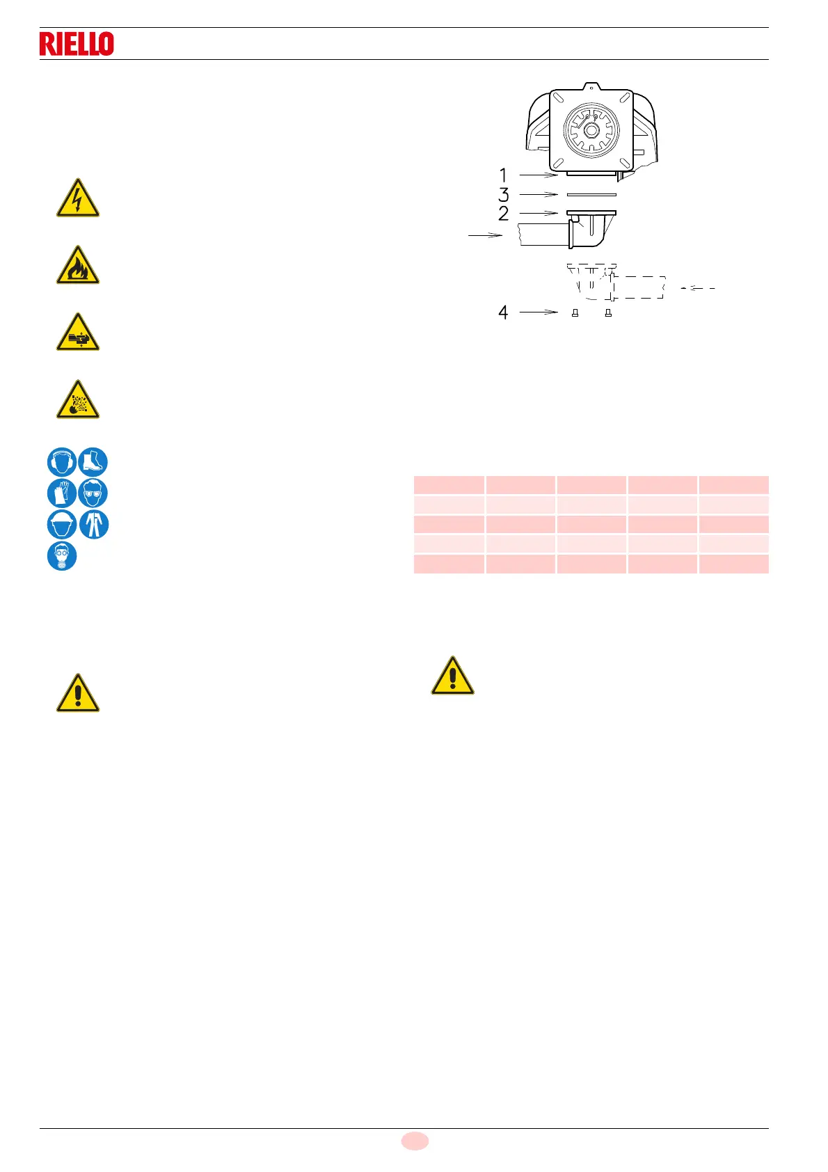
The train can enter the burner from the right or left side,
depending on which is the most convenient, see Fig. 24.
The gas train must be connected to the gas connection
1)(Fig. 24), using the flange 2), seal 3) and screws 4) supplied
with the burner.
See the accompanying instructions for the adjustment of the gas
train.
5.13.4 Gas pressure
Tab. I indicates the pressure drops of the combustion head and
gas butterfly valve depending on the burner operating output.
Tab. I
The values shown in Tab. I refer to:
– Natural gas G 20 NCV 9.45 kWh/Sm
3
(8.2 Mcal/Sm
3
)
– Natural gas G 25 NCV 8.13 kWh/Sm
3
(7.0 Mcal/Sm
3
)
Disconnect the power supply using the system
main switch.
Check that there are no gas leaks.
Pay attention when handling the train: danger of
crushing of limbs.
Make sure that the gas train is properly installed
by checking for any fuel leaks.
The operator must use the required equipment
during installation.
The gas solenoids must be as close as possible to
the burner to ensure that the gas reaches the
combustion head within the safety time of 3s.
Make sure that the maximum pressure necessary
for the burner is within the calibration range of the
pressure regulator.
kW
1 p (mbar) 2 p (mbar)
G 20 G 25 G 20 G 25
1250 5.2 7.8 3.0 4.4
1500 7.2 10.7 4.4 6.6
2000 11.3 16.9 7.7 11.4
2400 15.8 23.6 11.2 16.7
2650 19.4 28.9 13.6 20.3
Data of head thermal power and gas pressure
refer to operation with gas butterfly valve fully
open (90°).
 Loading...