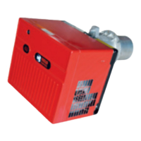
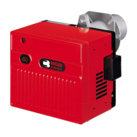
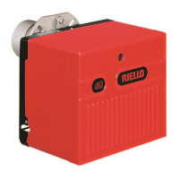
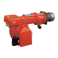
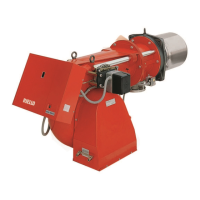
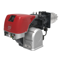
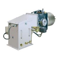
The Riello 40 G900 580T is a single-stage, forced-draught burner designed for use with natural gas or propane. It is manufactured by Riello, a company specializing in combustion technology. This manual provides comprehensive instructions for installation, operation, and maintenance, ensuring safe and efficient performance.
Function Description:
The burner's primary function is to provide a controlled flame for heating applications, such as boilers and furnaces. It operates in a single stage, meaning it has one fixed firing rate. The forced-draught design uses a fan to supply combustion air, ensuring optimal air-to-fuel mixture and efficient combustion. The burner is equipped with multiple interlocking safety devices to prevent unsafe operation, including a safety lockout feature that activates in case of flame failure or combustion air supply blockage.
Important Technical Specifications:
- Firing Rate: 250,000 to 900,000 Btu/hr.
- Fuel Type: Natural Gas or Propane.
- Electrical Supply: 120 Volts, 60 Hz, 1 phase.
- Motor: 233T, 4.3 Amps, 3250 rpm, 325 rad/s.
- Control Module: RMG 88.62.
- Gas Supply Pressures (with 1" gas train and 0" wc chamber pressure):
- Natural Gas: Min. 8" wc, Max. 14" wc.
- Propane: Min. 7" wc, Max. 14" wc.
- Manifold Pressures (with 1" gas train and 0" wc chamber pressure):
- Natural Gas: Min. 1" wc, Max. 3.35" wc.
- Propane: Min. 1.23" wc, Max. 5.2" wc.
- Combustion Chamber Size (Recommended Minimums): Minimum diameter of 16 inches for various MBtu/h outputs, with specific length recommendations provided in a chart.
- CO2 Levels: Max 10% for Natural Gas, Max 12% for Propane.
- CO Levels: Not to exceed 0.02% (200ppm) free air sample.
- Flue Gas Temperature: Recommended 350°F to 550°F.
- Ionization Current: Minimum 5 micro Amps DC for proper control box operation.
Usage Features:
- Step-by-Step Installation: The manual provides a detailed, step-by-step procedure for installing the burner, including bolting the combustion head, connecting the gas train, and electrical hookup.
- Combustion Head Setting: Instructions for adjusting the combustion head based on the desired firing rate, using an Allen screw and an elbow to align the air tube with set point numbers.
- Air Gate Adjustment: Manual adjustment of the air gate (damper) using locking screws to regulate combustion air for optimal performance.
- Start-Up Cycle Diagnostics: The control box features a diagnostic function with a RED LED indicator that provides pulse sequences to identify the cause of malfunctions during start-up.
- Resetting the Control Box: Instructions for resetting the control box and using visual diagnostics to troubleshoot lock-out conditions.
- Gas Train Layout: A typical gas train layout is provided, detailing both field-supplied and Riello-supplied components, including shutoff valves, pressure test points, regulators, and safety valves.
- Sediment Trap Installation: Specific instructions for installing a sediment trap and ensuring proper gas supply connections, including pressure testing procedures.
- Wiring Diagrams: Factory wiring diagrams are provided for both 120V and 24V control systems, outlining connections for the motor, control module, ignition transformer, and safety devices.
Maintenance Features:
- Routine Maintenance: The manual outlines routine maintenance tasks to be performed at intervals of 2 months and annually.
- 2-Month Maintenance:
- Visually check the flame (if an observation port is available).
- Check and clean the air intake louver to remove fluff, dust, or pet hair buildup.
- Annual Maintenance (by a qualified service technician):
- Check and clean the burner distributor head and mixing plates.
- Check, clean, adjust, or replace the ignition electrode.
- Check, clean, adjust, or replace the flame sensor rod (ionization rod) for dirt or carbon buildup.
- Check manifold gas pressure.
- Check all burner adjustments.
- Clean all exposed parts and components.
- Repeat combustion tests.
- Chimney Check: Annual inspection and cleaning of the chimney by a qualified service technician.
- Safety Lockout: The burner is equipped with a safety lockout feature indicated by an illuminated red button on the front cover. Instructions are provided for resetting the burner and when to call a service technician.
- Spare Parts List: An exploded view diagram and a detailed list of spare parts with their respective codes and descriptions are included for easy identification and ordering of replacement components.