GB
20027974
12
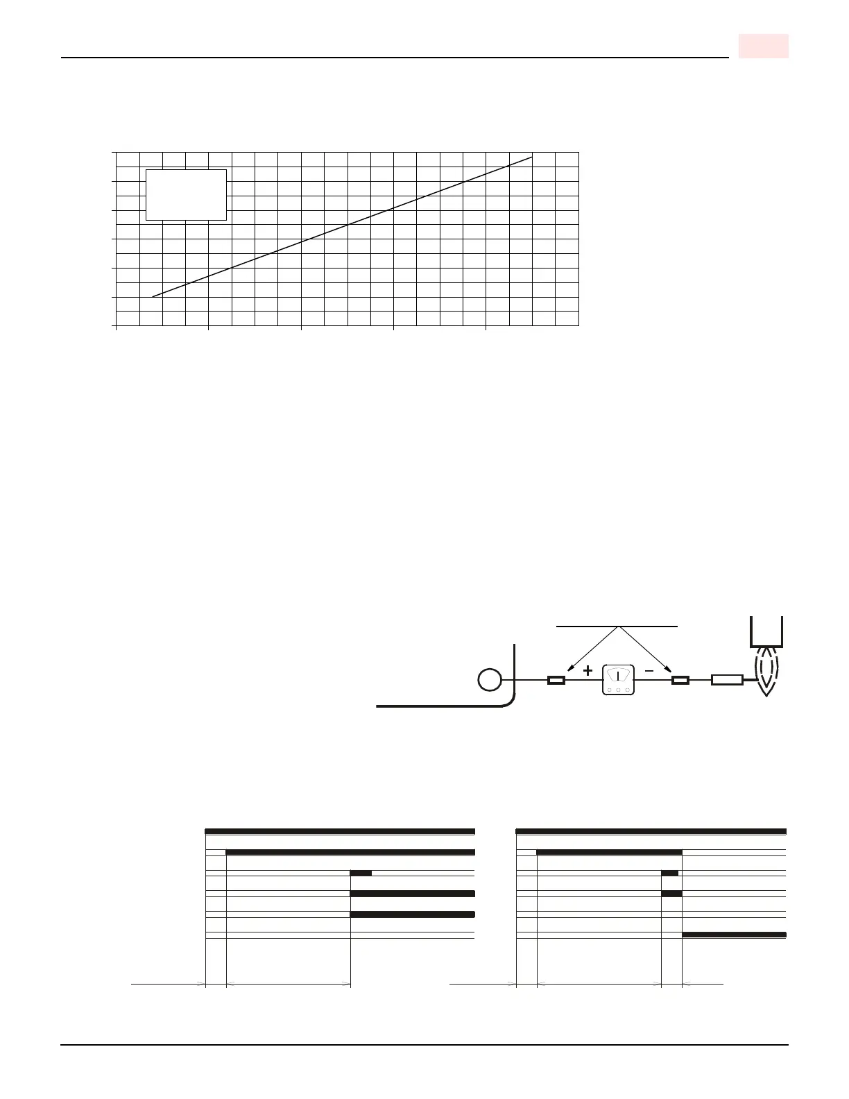
COMBUSTION CHAMBER SIZE
NOTES:
1) Sizes shown above are for cylindrical or wet base boilers, or air cooled heat exchangers.
2) To size the chamber in applications other than wet base boilers, you must calculate area in square inches of the
combustion zone required to give you a grate area or floor area to match the BTU inputs according to local authority.
3) Recommended firebrick or cerafelt material has a continuous run limited to 2400 degrees Fahrenheit and a melting
point of 3000 degrees Fahrenheit.
COMBUSTION CHECKS
CO
2
It is advisable not to exceed a measured reading of 10% CO for Natural Gas or 12% CO for Propane Gas
taken with the burner cover in place, to avoid the risk of the formation of CO due to minor changes in wind/draft
conditions which may occur.
CO For safety reasons, the value of .02% (200ppm) free air sample must not be exceeded.
IONIZATION CURRENT
The minimum amount of current necessary for
the control box to operate properly is 5 micro
Amps DC.
To measure the ionization current, disconnect
the red wire connector and insert a DC microme-
ter in series with control box terminal 9 and the
ionization probe, which senses the flame.
BURNER START-UP CYCLE
COMBUSTION CHAMBER SIZE
Recommended Minimum Sizes
Length - Inches
32
28
20
16
280
40
MBtu/h
36
24
440 600 760 920
MINIMUM
DIAMETER
16 inches
D7415
Ionization probe
Red wire connect
Control box
terminal block
D5006
9
3s40s
40smax. 2s
max. 2s
D4172
Lock-out, due to ignition failureNormal
Thermostat
Motor
Ignition transformer
Valves
Flame
Lock-out
 Loading...